|
Title: |
1884 Image-Watertown Steam Engine Co., Steam Engine |
|
Source: |
The Engineer's Handy Book 1884 pg 195 & The Practical Steam Engineer's Guide 1890 pg 80 |
|
Insert Date: |
3/2/2011 7:18:07 PM |
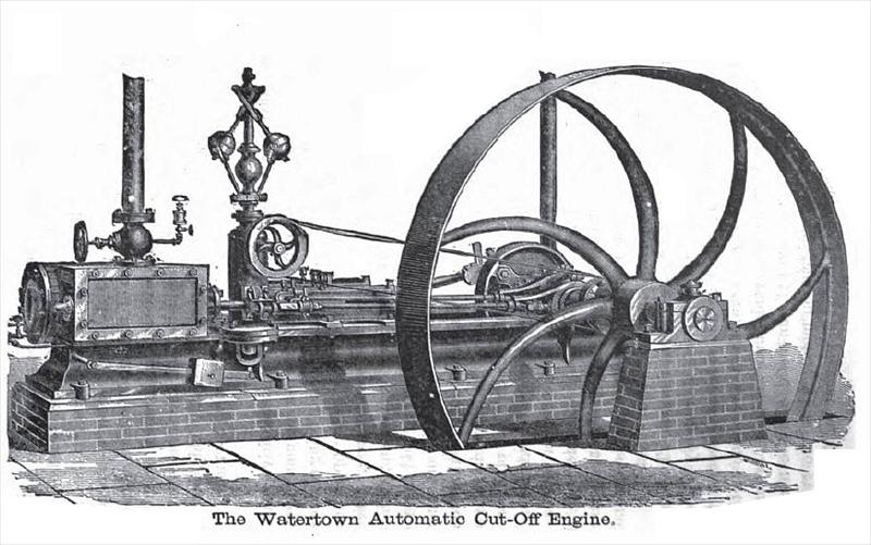
The Watertown Automatic Cut-off Engine.
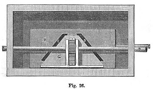
Fig. 25 gives a general view of the Watertown Engine, and Fig. 26 shows the cut-off valve. It will
be seen that there are two eccentrics, and therefore two valves. The eccentric nearest the pillow-block is connected to the main valve, which is of the ordinary pattern, with this exception, that the steam instead of passing the edge of the valve, is taken through it, by means of the ports C and D, shown in Fig. 26.
H represents the back of the main valve, which is also the seat of the cut-off valve G. F represents the stem of the main valve, and B the stem of the cut-off which is continued on through the end of the steamchest, and is held steady while the engine is working by means of a horn at A. The reader will notice that there is a rack cut in the back of the cut-off valve, which engages the teeth of a small gear on the valve-stem, and from this device will at once come to the conclusion that the adjustment of the cut-off is accomplished by rolling the valve-stem. This, as a
matter of course, will raise and lower the cut-off valve by means of the rack and pinion, thereby opening or closing the ports.
Directly under the governor there is a disc on the valve-stem, with teeth cut on the periphery about half the circumference, and these teeth engage a rack connected with the governor spindle; consequently, as the balls of th .governor rise and fall, a proportional motion will be transmitted to the cut-off valve.
In order to make this motion positive and reliable at all times, an important improvement has been made in the manner of suspending the governor balls. The point of suspension, instead of being on the same side of the spindle as the ball, is carried to the opposite side, thereby greatly increasing the power and sensitiveness of the governor.
To determine the point at which the engine is cutting off while running, the plain part of the disc which is connected with the governor and valve-stem, has marks and figures upon it, each mark indicating a point in the length of the stroke. There is a point which coincides with these marks. A glance at this device will show at once the point at which the cutoff takes place. To increase or diminish the speed, a counter-weight is attached to the end of the governor spindle, under the steam-chest. These engines are also built with a plain slide-valve, and with cut-off adjustable by hand.
The bed-plates are very solid, heavy, and substantial. The cylinder is jacketed to prevent radiation. The piston consists of three rings and springs. The piston-rod is screwed to the cross-head and secured by a jam-nut, admitting of adjustment at any time, as it wears.
The steam-chest is full length of the cylinder, reducing the clearance space to a minimum. These engines are justly numbered among the "standard" engines of this country. |
|
 1884 Watertown Steam Engine Co., Steam Engine
 1884 Watertown Steam Engine Co., Steam Cut-Off Valve
|
|