|
Title: |
1884 Image-Woodruff & Beach Iron Works, High Pressure Steam Engine |
|
Source: |
The Engineer's Handy Book 1884 pg 125 |
|
Insert Date: |
4/6/2012 7:28:56 PM |
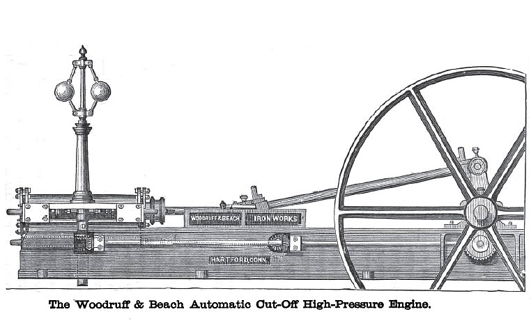
The Woodruff & Beach Automatic Cut-Off High-Pressure Engine.
The cut on the opposite page represents the Woodruff & Beach high-pressure automatic cut-off engine. Fig. 1 shows a section of the cylinder-valves, steam passages, and exhaust passages. Fig. 2 is a back view of the cylinder, steam-chests, valve-gear, etc. With the exception of the Corliss, it is the oldest variable cut-off engine in the country, and one that has undergone fewer changes in its mechanism than any other. Those who remember it thirty years ago, will fail, at the present day, to discover much difference from its general appearance. For more than a quarter of a century it has successfully competed with such engines as the Corliss, and it has always sustained a high rating in the scale of comparative merit. The bed-plate, as will be observed, is of the ordinary box O. G. pattern, to which the cylinder-guides and pillow-blocks are bolted and dowelled in such a manner that the possibility of their getting out of line is entirely obviated. The steam-valves, which are of the double poppet form with bevelled faces and seats, are located at the back of the cylinder at each end, horizontal with its axis. Their stems project inward, and, owing to the peculiar shape of the cam which gives the motion, the opening and closing is done very quickly and almost noiselessly. They have independent adjustments, so that the steam lead may be varied to meet any requirement without interfering with the rest of the valve-gear. The power required to work the valves in these engines is very slight, and as the cam lug and the ends of the valve-stems are made of hardened steel, they show no perceptible sign of wear after years of use. The exhaust-valve, which is cylindrical in form and has a very convenient arrangement for taking up the wear and preventing leakage, is placed at the bottom of the cylinder, and communicates with it by its own ports or passages, which are entirely separate from those of the steam-valve. An equilibrium of pressure is maintained by the exhaust taking place through the interior of the valve, and as its stroke is very short, the liability to wear is slight. Its motion is derived from a transverse shaft under the centre of the guides, carrying an eccentric, and driven by bevel gears. Owing to the position of the exhaust openings at the bottom of the cylinder, and their ample size, the exhaust is very free; the discharge of any water that may accumulate from condensation or from priming in the boilers is rendered easy, and all danger of accident from this cause is obviated.
The governor, which is very powerful and sensitive, and of a kind that is admirably adapted to these engines, is located centrally between the steam valves, and receives its motion from a longitudinal shaft, supported on bearings attached to the bed-plate, and driven by a spur and bevel-gear from the crankshaft. Its spindle passes through a compound eccentric carrying a movable cam-lug, which, by its rotation, gives the opening or outward motion to the valves, in which direction it is positive; while the closing, although controlled by the cam, is effected by the pressure of the steam upon the unbalanced area exposed at the outer end, and is assisted by a spiral spring. In the bore of the inner eccentric is an inclined or spiral slot for the reception of a key attached to the governor-spindle, from which the eccentric receives its motion. As the key is raised or lowered by the variations of the governor, the inner eccentric is turned to the right or to the left, and the cam-lug moved in or out, as the case may be, thereby giving the necessary opening to the valve, and cutting off the steam at the right point to allow of the proper degree of expansion. As the cam-lug is at all times in the same relative position to the outer shell of the eccentric, the lead of the steam-valve is not affected by the variations. The expansion-gear of these engines is one of the most ingenious,
simple, and effective mechanical devices that can be employed for that purpose. Its operation may be explained as follows: The cam, marked C, cuts off the steam with certainty at any part of the stroke, the motion being produced automatically by the action of the governor upon it, throwing it more or less out of centre with the spindle of the governor; the rotation of the balls being more or less rapid, the eccentricity of the cam determines the amount of steam admitted to the cylinder. To produce this effect the cam is made of two pieces. C is a hollow shell or cylinder, with a part of one end formed into a cam proper. Throughout the whole length of this piece, upon the inside, there is a spiral groove cut to receive one end of a feather, by which its pitch or eccentricity is regulated. The inside piece, D, is a hub which exactly fits into the hollow of the cylinder, C, and has a socket, e, into which the spindle of the governor is secured, the other end, d, forming a journal or bearing with a bevel-wheel on its extremity, to transmit the motion from the crank-shaft gearing to the governor and cut-off. There is a hole throughout the length of the inside piece, D, which is continued through the spindle of the governor, and which contains the rod which connects the cam with the governor. This hole is eccentric to the outside surfaces of D and C, but is concentric with the collar, /, and with the governor-rod. Both pieces, C and D, are connected by a feather, one piece of which is of a spiral form, and the other straight; the two being connected together by a stub which fits into a hole or bearing in the spiral piece, so that the latter can turn on the stub and accommodate itself to the groove in which it works. The spiral part of the feather works in a spiral groove in the inside of the shell, C, and the rectangular piece works in a straight groove on the inside of the hub, D, the inner part of the rectangular piece being fastened to the governor-rod, so that the feather is permanently connected with the governor. When the several pieces are put together the cam is complete, as shown in Fig. 4, and it operates as follows: Motion is communicated by gearing from the crank-shaft to the bevel-wheel on the end of the piece, D, as well as to the spindle of the governor, which is screwed into the socket on D; as the balls rise or fall through change in the centrifugal force, due to the variation in the speed of rotation, they raise or depress the governor-rod, which passes through the spindle, and the piece, D, which is attached to the feather thereby raising or depressing it. This feather acting on the spiral groove instantly alters the lift of the cam, and regulates the amount of steam admitted to the cylinder. By these means any speed may be selected at which the load of the engine is to move, and any variation from that will be instantly felt by the governor, and corrected. There is no jar in the working of the parts; the feather moves noiselessly in its grooves; the governor-rod moves up and down through the spindle and the piece D, and can be regulated to give any required opening of the steam-ports to suit the work to be done. The Woodruff &. Beach engines are very simple in design, and have the reputation of being very durable and economical. Absence of complication in the valve-motion, and the ease with which all the working parts can be adjusted, are valuable features. |
|
 1884 Woodruff & Beach Iron Works, High Pressure Steam Engine
 1884 Woodruff & Beach Iron Works, High Pressure Steam Chest
 1884 Woodruff & Beach Iron Works, High Pressure Steam Chest
|
|