|
Title: |
1889 Image & 1890 Ad-Providence Steam Engine Co., Greene Steam Engine |
|
Source: |
Industries of Providence 1889 pg 84 & Mechanics Magazine Feb 1890 pg VII |
|
Insert Date: |
11/9/2012 1:15:39 PM |
The illustration on the opposite page represents the Improved Greene Engine, which is built only at the works of the Providence Steam-Engine Co., at Providence, R. I.
In 1821 John Babcock established the works now known as the Providence Steam-Engine Company, with the small capital of $5,000.
The facilities of this company now are such that it could easily turn out a yearly product of over $1,000,000—or two hundred times the approximate value of its first year's product.
It is now under the general management of Rathbone Gardner as President, Wm. B. Waterman, Treasurer, and T. W. Phillips, Manager and Secretary. John Babcock built his first engine about 1830; it was a beam engine, and after the general principle of Boulton & Watts. One of his first engines was made for Jacob Dunnell, of Pawtucket, R. I., and he built the first engine that was applied to the running of cotton machinery, which went into a mill at Bristol, R. I. Frederick E. Sickles patented his cut-off in 1842. This consisted in detaching the valve entirely from the mechanism that worked it, and allowing it to drop automatically into its place. He brought his plans to this shop, and the first application of the principle was made here. Zechariah Allen, of Providence, R. I., who was a natural mechanic and had given great attention to the steam engine, improved upon Sickles's device by attaching the governor to the mechanism, so that the cut-off would occur at any point of the stroke desired. This is the leading feature of the Corliss engine, which was patented by Mr. Corliss in 1849.
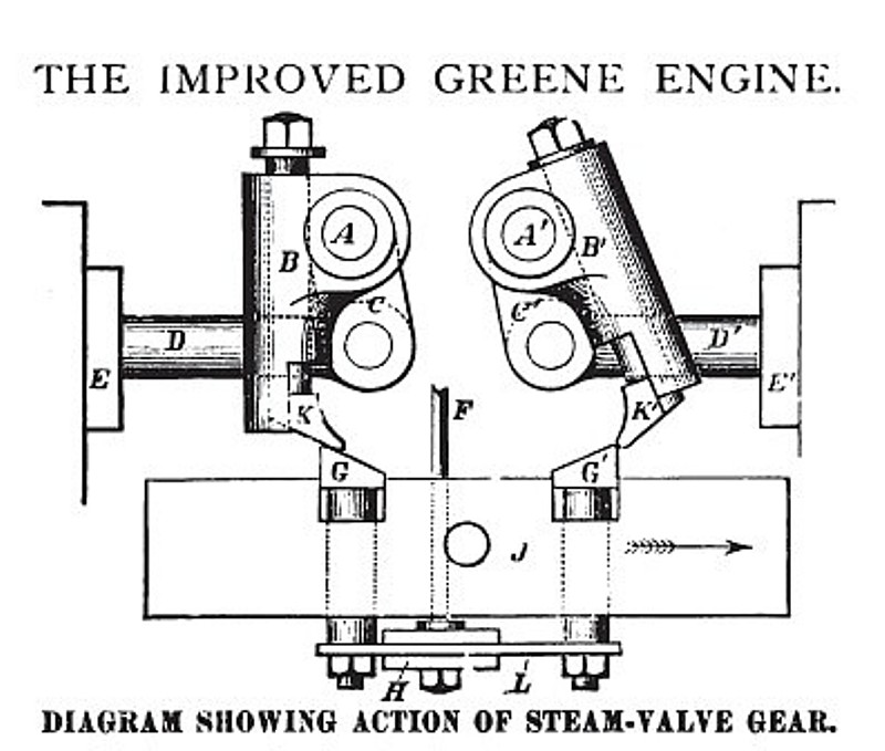
In 1855 Mr. Noble T. Greene patented his cut-off, which was also a liberating valve gear, and the company built the engine under royalty until their construction was enjoined by George H. Corliss. At the expiration of the Corliss patent they occupied two years in the selection of an engine which was to furnish them with a business, and not finding any which met with their approval, they bought the Greene patent, and designed an engine which contains the valuable features of the Greene engine, but embodied in such form as to disarm criticism. This engine they have designated as the Improved Greene Engine, to distinguish it from the original Greene. As this article does not permit anything more than a record of the inception and description of the engine, and a slight historical record of the establishing of the business, the following description of the engine will perhaps be interesting to those who are not familiar with its construction. are the two rock levers; BB' the sockets attached to them and within which the toes KK' are contained; CC the arm of the levers attached to valve stems; DD' the valve stems; EE' the steam-chest; F the governor-rod; GO' the tappets; L the gauge-plate; H the gauge-plate guide; and J the sliding bar.
The sliding bar J is shown moving in the direction of the arrow, causing the tappet 0' to operate upon the toe K', giving an opening movement to the valve-stem D', the tappet G meanwhile passing under and lifting the toe K. The amount of opening of steam-valves is determined by the height of the tappets G G', the positions of which are always under control of the governor. The toes drop by gravity, no springs being used, thus relieving the governor of all strain while tripping.
The bed-plate is of the girder pattern, symmetrical in appearance, and of ample strength. The slides are cast separate, and secured to bed-plate by dowels and bolts. The main journal-boxes are made in four pieces, and provided with set-screws and check-nuts, which permit of convenient and accurate adjustment. The governor is of the PorTer pattern, and is driven by a flat belt from the main shaft. The valve gear is detachable, and so controlled by the governor that the cutting off may be effected from zero to three-quarters of the entire stroke. The valves are four in number—two steam and two exhaust—and are of the flat-slide pattern. The power which moves them is applied parallel to and in line with their seats, so that they cannot rock or twist—thus obviating the tendency to wear unevenly. The steam-valves when tripped are shut by a combined action of a weight and the pressure of the steam on the large valve-stems, thereby ensuring a quick cut-off, and the positive closing of the port, under all circumstances of speed and pressure. The steam-valves are operated by toes on the inner ends of two rock-shafts that connect with the valve-stems outside the steam chest. The outer ends of the rock-shafts are furnished with steel-tipped toes.
There is a sliding bar carrying tappets, which receives a reciprocating rectilinear motion from an eccentric on the main shaft. Below the sliding bar is a gauge-plate connected with the governor, which receives an up and down motion from a reverse action of the governor balls.
The tappets in the sliding-bar are attached to the gauge-plate, and elevated or depressed in the bar by the action of the governor. As the sliding-bar moves in the direction of the arrow, one of the tappets is brought in contact with the inner face of the toe on the rock lever, causing it to turn on its axis, thereby opening the steam-valve at one end of the cylinder. At the same moment the other tappet comes in contact with the outer face of the other toe, and as the surfaces are beveled the toe is forced up into the socket until the tappet passes under, when it drops by gravity alone into its original position to be operated upon in its turn, when the motion of the sliding-bar is reversed.
As a result of this motion, the tappets always give the valves the same lead, and as the bar moves in a straight line, while the toe describes the arc of a circle, the tappet will pass by and liberate the toe, which is brought back to its original position by a weight and the steam pressure on the large valve-stem, which thus closes the valve and cuts off the steam. The liberation of the toes will take place sooner or later according to the elevation of the tappets; that is, the lower the tappets are, the sooner the toes will be liberated, and vice versa. By the elevation or depression of the gauge-plate, the period of closing the valves is changed, while the period of opening them remains the same. The adjustment of the gauge-plate is effected directly by the governor.
Both the exhaust-valves and seats are convenient of access, and removable from the outside of cylinder. The valves receive their motion from a separate eccentric, thus allowing of easy adjustment, without interference with the steam-valve mechanism. All the connections are on the outside, are few in number, and have ample bearing surfaces, ensuring freedom from rapid wear and derangement.
A safety stop-motion is combined with the governor, preventing the admission of steam should the governor belt run off or break.
The cross-head gibs are directly opposite the centre of pin, thus avoiding any cross strain upon the piston-rod; a lack of attention to this point has been the cause of many serious accidents. The steam-ports are large, thus ensuring the full pressure of steam to the point of cut-off. The engine is extremely sensitive to the action of the governor, and is, therefore, particularly adapted to those situations where perfect regulation is required, All parts are well proportioned, made of the best material, accurately fitted, and highly finished. (These engines are manufactured by the Providence Steam-Engine Co., Providence, R. I.)
The Steam User 1890 pgs 34-37 |
|
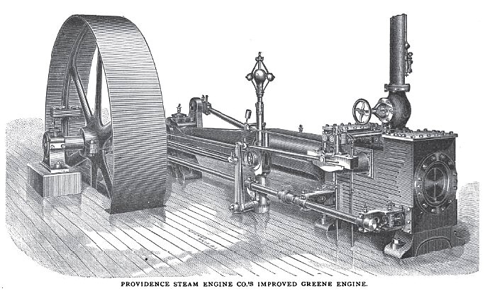 1889 Providence Steam Engine Co., Greene Steam Engine
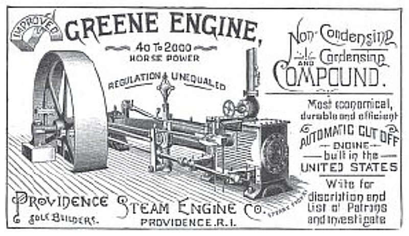 1890 Providence Steam Engine Co., Greene Steam Engine
 1890 Providence Steam Engine Co., Greene Steam Engine (Steam Valves)
|
|