|
Title: |
1896 Image-Putnam Machine Co., 18" Engine Lathe (Part 1) |
|
Source: |
Illustrations and Details of American Machine Tools-MIT 1896 pg 4,5 & 6 & Modern Mechanism 1895 pgs 458-461 |
|
Insert Date: |
12/15/2012 5:51:11 PM |
The Putnam Engine-Lathe.-Figs. 11 to 16 illustrate a new standard lathe recently brought out by the Putnam .Machine Co.. of Fitchburg, Mass. Figs. 14 and 15 represent the bed in longitudinal and cross-section. This is a heavy U-shaped casting, strengthened by a strong truss extending from end to end. This truss is stiffened by a bead at the top, and is connected by lateral webs to the sides of the bed. Ribs placed at suitable distances apart extend from the under side of the top down the sides, firmly uniting the members of the bed. The front carriage A is made higher and larger than the back A. The construction of the head-stock is shown in Fig. 12. The boxes are conical-shaped on the outside, straight on the inside, and fitted to correspondingly tapered holes, or seats, in the metal of the head-stock casting. They are split for adjustment, and are threaded at their ends for the adjusting-nuts NN. The nut N has a spherically shaped projection, and in addition to serving as an adjusting-nut for the back spindle-box, is threaded from the step S, which through a rawhide collar takes the thrust of the spindle 0 is a lock-nut to secure the step against turning after it is properly adjusted. A steel collar is fitted with a feather to slide on the spindle, and is held in position by nuts. This, being adjusted to contact with the end of the box, holds the spindle from end-long motion in one direction, while it is held from motion in the other direction by the step S. This construction is intended to prevent disturbance of adjustment due to contraction and expansion from changes of temperature. When adjusted, the boxes are restrained from turning in their seats by the adjusting-nuts, which are always screwed against the casting; but while being adjusted to the spindle, pins in the outside of the boxes St in grooves in the seats, these grooves holding the boxes from turning around, but permitting lateral movement. A series of holes is drilled around the circumference of the boxes, so that by placing the pins in different holes the boxes may be occasionally partially rotated in their seats, thus equalizing the wear, and tending to keep the spindle in a central position. The handle L (Fig. 12) is for disengaging or changing from coarse to fine or fine to coarse feed, which is done by means of the following arrangement: The feed-gear inside the head is on a feathered shaft, and may, by moving the handle to the two positions shown by dotted lines, be geared to either the gear on the spindle or that on the cone, the difference in feed between the two positions being 9 to 1. This, which is applicable to either longitudinal or cross feed, or to screw-cutting, with the changes of both gear and belt-feed to the feed-rod, provides for a great range of feed, from that fine enough for any purpose to that extremely coarse, for surface-work or for cutting screws or worms of coarse pitch. Fig. 16 (see part 2 image) is a section through the carriage and bed. The feed-rod is at the front and the lead-screw at the back side. To lock the nut and lead-screw, a rod extends across the carriage (on all lathes above 18 in. swing) from the front to the rear, where, by means of the pinion H, it connects with the plate I. The operation of bringing together or separating the half-nuts of the lead-screw is accomplished by turning the rod. The rack-gear and pinion-shaft is, by means of the yoke K, provided with a second bearing, the working strain coming between the two journals. To avoid the possibility of locking the nut to the lead-screw while the gear and rack are connected, or vice versa, a safety-pin is connected with the yoke A", and the hub of the lever that operates the lead-screw nuts has in it a hole to which this pin is fitted. This hole is in such a position that when the rod is turned to bring the nuts together on the screw it will not be in alignment with the pin. If, now, an attempt is made to raise the yoke so that the pinion will gear with the rack, the pin will come in contact with the plain surface of the hub, preventing its accomplishment. When the disk is turned to the position in which it stands when the nut is off the screw, the hole is in alignment with the pin, and the yoke may be raised to gear the rack and pinion together. If, when the rack and pinion are in gear, an attempt is made to connect the nut with the lead-screw, the pin will prevent the disk (and rod) from turning. This makes it impossible to do damage by the attempted operation of both screw and rod-feed at. the same time.
In Fig. 5 the tail-stock is shown in two sections. It has a long bearing on the ways, and an extension that serves for a tool-shelf. The front bearing is split for binding the spindle. To overcome the difficulty of moving it against the sliding-friction of the ways, wheels R are placed as shown, one at each side over the V's, These wheels are so mounted as to be free to move vertically a short distance, and are loaded by adjustable springs. When the tail-stock is loosened the springs tend to assume the load, thus transferring the weight to the wheels, and transposing the hard sliding to an easy rolling motion. The arrangement for clamping the tail-stock to the ways is shown at B. It consists of a binding-bolt and nut, the face of the nut being cam-shaped, to correspond with the cam-shaped washer underneath it, In tightening, the somewhat abrupt faces of the cams take up the slack motion by a slight movement of the handle, when the nut and thread bind the tail-stock rigidly. Similarly, in loosening the tail-stock the abrupt angle of the cams gives the necessary freedom with the same small amount of motion. The back-rest has a lever-handle lock-nut. |
|
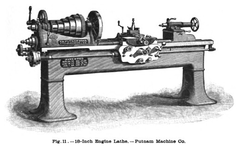 1896 Putnam Machine Co., 18" Engine Lathe
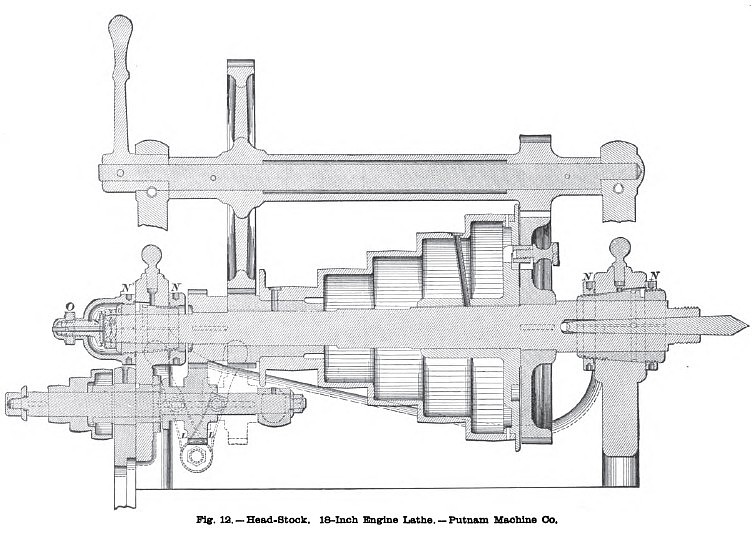 1896 Putnam Machine Co., 18" Engine Lathe Head Stock
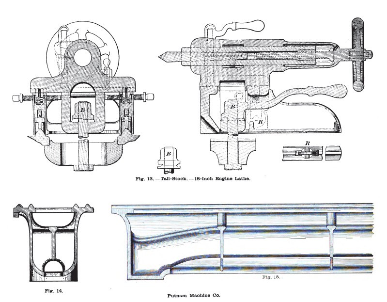 1896 Putnam Machine Co., 18" Engine Lathe Tail Stock
|
|