|
Title: |
Nelson W. Twiss, The Twiss Corliss Engine Valve Gear |
|
Source: |
The Engineer, V38, 15 Jun., 1901, pgs. 216-217 |
|
Insert Date: |
7/7/2026 12:30:18 PM |
THE TWISS-NELSON W. TWISS.
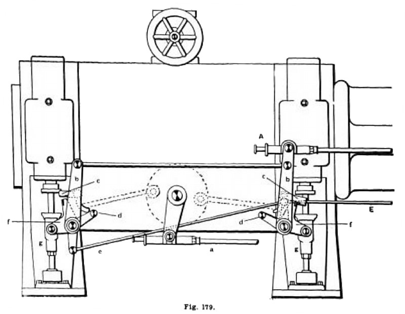
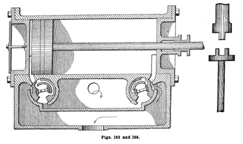
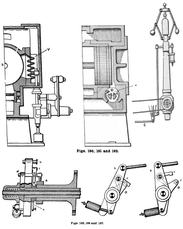
The Twiss engine is of the automatic cutoff type, and resembles the Corliss engine in many respects that is, in the general design of the frame, crosshead, connecting rod, governor and in minor details. The general arrangement of the valves in the Twiss engine is shown in fig. 183, which represents a sectional view of the cylinder and the main and cutoff valves. The main valve, which is cylindrical in form, is fitted to the bore of the chest, and is bored out so as to form the cutoff valve seat on its inner surface, the cutoff valve being contained within the main valve as shown. The stem of the main valve is also hollow, through which passes the cutoff valve stem. The stems are connected to the valve in the manner shown in fig. 184. The several parts of the releasing mechanism are placed on the valve stems, outside of the bonnet, in the following order (note fig. 185): Next to the bonnet is placed stop A and the knockoff cam a, which is actuated by the governor; then comes the long lever B, to which is attached the hook c, then the bell crank lever D, which is attached to the cutoff valve stem, and at the outer end of the cutoff valve stem is the spring case e, containing a spring as shown. The operation of this gear may be understood by referring to fig. 186 which shows the knockoff cam, lever B and the bell crank lever D, which actuates the cutoff valve. The other members have been omitted to avoid confusion. The three parts mentioned now occupy their proper positions at the commencement of the stroke. Fig. 187 represents the relative positions of the parts when the lever b has reached its extreme position to the left (in the drawing), and the cutoff valve as having been closed. The lever D is actuated by the spring in the spring case, the spring being now relaxed. When the lever b returns to the position shown in fig. 186, it winds up the spring, so that by the time the hook c engages the catch block d the spring will be wound up and ready to move the lever when it shall again be released by the hook. The movement of lever D is stopped at the proper point by the fixed stop a, on the end of the bonnet. This stop, however, only comes into play with a very early cutoff. It will also be noticed that as lever b returns to engage lever D, fig. 186, the piston in the dashpot is drawn outward, in other words the cylinder is drawn to the left and away from the piston, and remains so until the latter lever is released by the hook, when it is pushed into the cylinder and by the compression of a certain quantity of air its motion is cushioned, thereby avoiding any jar when it reaches the fixed stop A, on the bonnet. The operation of the valves in the chest corresponding to the movements of the releasing gear just described may be readily understood by the inspection of fig. 183, which represents the relative positions of the main and cutoff valves at the head end and at the commencement of the stroke of the piston.
SETTING THE VALVES.
To set the valves, first place the crank on the dead center nearest the cylinder. Then remove the bonnets on the front side of the engine. If marks representing the valve and port do not appear at the ends of the valves and on the valve seat they should first be made. Then place the valves in their proper center nearest the cylinder. Then remove the bonnets on the front side of the engine. If marks representing the valve and port do not appear at the ends of the valves and on the valve seat they should first be made. Then place the valves in their proper positions in the chests and have the eccentric turned from one dead center to the other to see that the valves open the ports wide, or an equal amount, at each end of the cylinder. If they do. the eccentric rod will be the proper length, but if one port is opened farther than the other the eccentric rod must be lengthened or shortened, as the case may be. until both ports are opened an equal amount when the eccentric occupies the dead centers.
Now turn the eccentric to the dead center nearest the cylinder. The port at the head end of the engine will now be wide open. Have the eccentric turned around on the shaft in the opposite direction to that in which the engine is to run until the main valve shall have dosed the port to within one-thirty-second inch. Have the eccentric fixed to the shaft at this point. Then turn the crank to the opposite dead center and see if lite opposite steam port—the one nearest the crank—is open an equal amount. If it is not, but is open too far or not quite enough, adjust it by moving the valve and by lengthening or shortening the eccentric rod. Care must be exercised in doing this, however, for if the lead is not right on the crank end and is adjusted by altering the length of the eccentric rod, it must be evident that this will disturb the valve at the head end. Therefore, when an adjustment of the valve mentioned is made, the crank must be again turned to the dead center nearest the cylinder and the lead of the valve at the head and adjusted by means of the right and left connections between the two vertical levers on the main valve stems. When the crank is on the center nearest the cylinder, the hook should have just engaged the catch block on the bell crank lever and the cutoff valve must then have opened the ports in the main valve wide. The stop next to the bonnet should be adjusted as to permit the hook to engage the catch block and no more. If this has been properly attended to and the main valves properly set. the ports in the main valve (not the cylinder) will be found to be open wide.
To equalize the cutoff turn the engine slowly in the direction in which it is to run until the cutoff, say on the head end occurs. Measure along the guides the distance the piston has moved and lay off the same distance beginning at the opposite end of the guides. Now have the crank turned in the same direction as before, past the center, until the crosshead reaches the line where the cutoff should occur. If it does not occur at the proper point, the governor rod connected to the knockoff cam corresponding to the valve, which fails to cut off properly must be lengthened or shortened until, upon bringing the crosshead slowly up to thee line, the valve finally closed at the proper point. This may require a few trials before exact results are attained. The speed of the engine may be varied by adding to or taking from the weights suspended from the governor. To reverse the direction of rotation in this engine, proceed in the same manner as previously described, remembering that when setting the eccentric, it is to be turned in the opposite direction to that in which it is desired to have the engine run.
US Patent: 1,006,808
https://www.datamp.org/patents/displayPatent.php?number=1006808&typeCode=0 |
|
 The Twiss Corliss Engine Valve Gear
 The Twiss Corliss Engine Valve Gear Sectional View
 The Twiss Corliss Engine Valve Gear Parts
|
|