|
Title: |
1908 Article-Gould Balance Valve Co., Gould Balanced Slide Valves |
|
Source: |
Walschaert Value Gear Breakdowns and how to Adjust Them, 1908, pgs. 83-88 |
|
Insert Date: |
8/2/2024 4:39:17 PM |
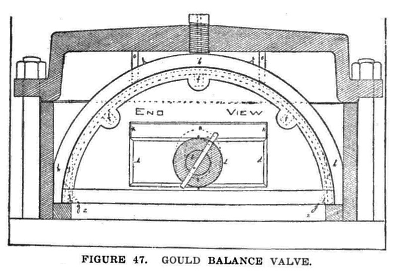
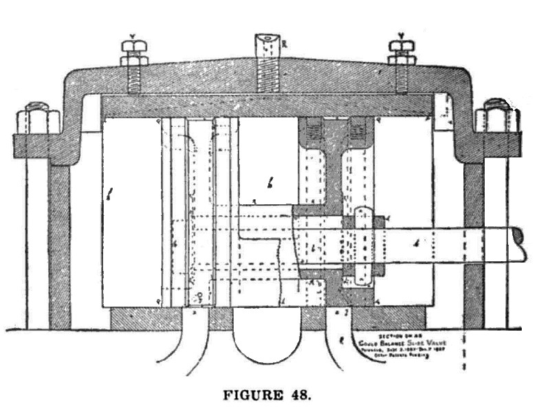
Figs. 47 and 48 are sectional views of the Gould balance slide valve, Fig. 47 being an end sectional view of the valve, valve cover and steam chest, and Fig. 48 is a vertical side sectional view of the same.
Referring to Fig. 47 H, is a loose cover that fits over the top of the valve, and is prevented from having too much longitudinal movement by stops c, c. This move
ment should never exceed 1-16 of an inch over all.
The space occupied by the packing is designated by the dotted lines in the semi-circle, and this packing is enclosed in the pockets f, f, f.
The letters k, k, represent a chipping strip upon the rear end of the valve, which may be faced off so that the back end of the yoke d, may fit it.
The letters n, n, represent the sleeve, which is cast solid to each wing of the valve, and extends across the cavity o, in order to contain the valve stem b.
The cavity o, is oblong in shape in order that the vertical movement of the valve may not bind upon the valve
stem.
The letters g, g, Fig. 47 designate two small holes drilled in the face of the valve for the purpose of establishing communication between the port z, and the cavity x, shown in Fig. 48.
Small ribs e, e, are cast upon the top of the valve cover h, in order to prevent the valve oil from running down the sides of the cover.
These ribs e, e, also cause the oil to be distributed to the end of the cover, thereby effecting a more perfect lubrication of the valve and seat.
Fig. 48 is a side sectional view of the valve, in which the packing rings are shown, held up by the spiral springs on one end of the valve, while the dotted lines on the opposite end of the valve designate the spring pockets.
Two cavities x, x, Fig. 48 extend around the outside faces of each end of the valve, while the packing as shown is placed upon each side of these cavities x, x.
The area of cavity x should always slightly exceed the area of the steam port z, in order that when port z, is filled with steam, and communication established with cavity x through hole g, (shown also in Fig. 47) the pressure in cavity x will at least equal the port pressure, and the valve will be held down on its seat.
It will be observed that a practically perfect balance may thus be obtained, the degree of perfection depending upon the location of the packing rings, relative to the outside edge of the valve, and the giving of the proper area to cavity x.
The check stubs y, y, Fig. 48, in the top of the steam chest cover are for the purpose of regulating the vertical movement of the valve cover h and preventing it from lifting too high from the valve.
It will be observed that these stubs do not quite touch the valve cover, being adjusted to allow a slight movement in a vertical direction.
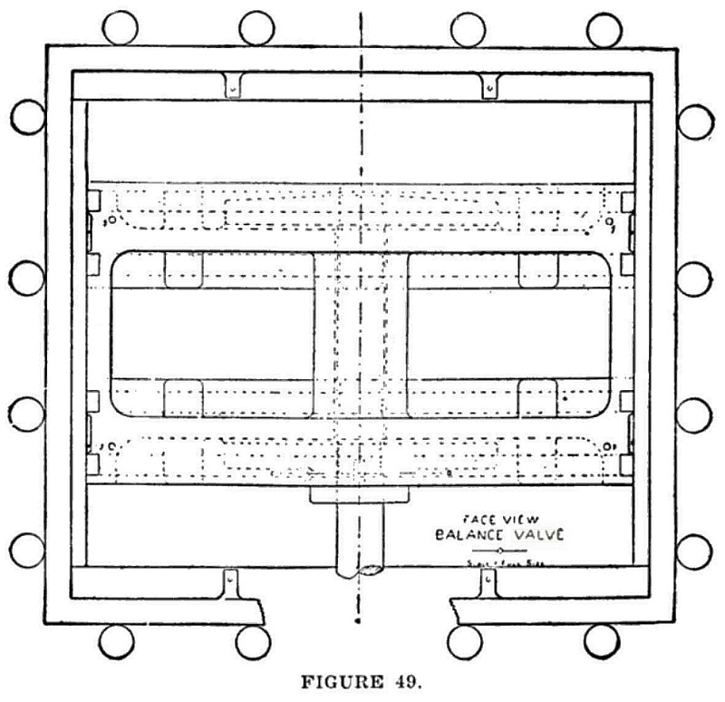
Letters 1, 1, see Figs. 47 and 49, designate a web that holds the bottom of the wings of the valve firmly together
in one piece and prevents any leakage of steam into the exhaust, which might occur if the valve cover was raised from the seat.
This valve is semi-circular in form and is constructed in the following manner.
The valves and their covers should fit iron to iron when they are cold, for the reason that when the cover becomes hot it expands a little more than the valve does, which leaves the valve free to move perfectly easy under it.
When it becomes necessary to face the valve the same amount of iron should also be planed off of the bottom edge of the valve cover, thus causing each to assume their normal position relative to each other, and as cavity of in the valve through which the valve stem passes is made oblong vertically, it will readily be seen that facing the valve will not affect the valve stem in the least.
When the exhaust is being planed out the tool should not be allowed to cut through line 1 shown in Fig. 49, which is a face view of the valve, and shows the form of the exhaust.
The sizes of the ports will of course have to be governed by the sized engine upon which the valve is to be used.
The packing rings should have at least five-eighths of an inch face with a depth of one-half inch.
The valve stem should be at least 11/2 inches in diameter, and the stops c, c, Fig. 47, should not be less than 5% of an inch in width.
The valve cover should finish 14 inches in thickness, in order that there will be no danger of its ever becoming distorted, or out of shape. This thickness would also permit of it being bored out the second time to fit the valve.
The depth of the cavities x should not be less than % of an inch and the diameter of the hole g, should be not less than 3-16 of an inch.
The diameter of the bolts y should be not less than 3/4 of an inch.
The springs that are designed to hold the packing should be made of about No. 70 steel wire so that the pressure on them would be very light for the reason that if these springs are too stiff they will cause the packing to wear too fast or might hold the cover up from the valve when steam was not being used.
US Patent: 912,372
https://www.datamp.org/patents/displayPatent.php?number=912372&typeCode=0 |
|
 1908 Gould Balance Valve Co., Gould Balanced Slide Valves
 1908 Gould Balance Valve Co., Gould Balanced Slide Valves
 1908 Gould Balance Valve Co., Gould Balanced Slide Valves
|
|