|
Title: |
1908 Article-Gould Balance Valve Co., Gould Balanced Slide Valves |
|
Source: |
Walschaert Value Gear Breakdowns and how to Adjust Them, 1908, pgs. 78-83 |
|
Insert Date: |
8/2/2024 4:27:08 PM |
Figures 44 to 49 serve to illustrate the construction and operation of the Gould balanced slide valves, of which there are two styles.
These valves are the invention of Mr. W. F. Gould of Des Moines, Ia.
The form known as the "Quick action valve", Fig. 44, deserves special attention.
Heretofore it has been the generally accepted belief among practical men that it would be impossible to prevent the valve from lifting off its seat if all the pressure were removed from the top of the valve, but the action of the "quick action valve" appears to refute this theory.
The principles of the Gould balanced valve are similar to those of the piston valve.
Either form of the Gould valve may be applied to the ordinary flat valve seat.
Two methods of balancing are employed, one form of which, the "quick action valve" may be used with either a flat pressure plate, or a semi-circle balance plate, and promises to be an important rival to our best forms of balance valves.
For the other form of valve the balance is obtained by means of a semi-circular balance plate fitted into the steam chest lengthwise.
It is not bolted to the cover like most pressure plates, but rests on the valve seat. It has lugs that are closely fitted on the ends to prevent it from moving lengthwise, while the pressure on its back serves to hold it to its seat.
The top of the valve is also a semi-circle in form, slightly smaller than the plate and has balance strips set into it which bear against the plate in the usual manner.
A small port at each end permits live steam to enter between the valve and the pressure plate, which is permitted to cover sufficient area to overcome the back pressure from the cylinder, thereby obtaining almost a perfect balance.
In construction the two balance plates, (one for each valve) are first planed off on the edges, then the two are clamped together and bored out to their required size.
The valves are finished in a similar way, first the two faces are planed off, then clamped together and turned off in a lathe, and made a little smaller than the pressure plate.
When the valve requires facing, the same amount is taken off the bottom edges of the pressure plate also, thereby retaining their original positions, and the plates automatically adjust themselves to any inequality due to the wear of the valve.
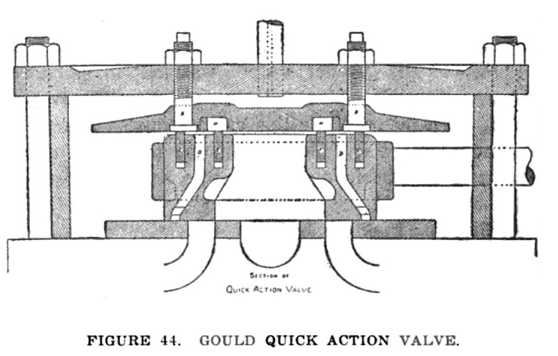
Fig. 44 is a sectional view of the quick action valve, and shows the relative positions of the small ports D, D at either end of the valve, to the ports leading to the cylinder. (Not lettered.)
The valve cover A is supported by four bolts to the steam chest cover, in such a manner as will permit of the cover A to be raised or lowered at will. H, H are ports in the base of the cover running longitudinally parallel to the steam ports.
The ports D, D already referred to are longitudinal cavities in each end of the valve, and should be of the same length as ports H, H and nearly as long as the steam port that leads to the cylinder.
E, E are packing bars placed on each side of the cavity D in the top of the valve in such a manner that the distance between them is of very little more area than the width of the steam port, for the purpose of holding the valve down when the steam port at the end of the valve is filled with steam.
In the operation of the valve as shown herein, when the valve is pulled back so as to open the steam port, it will be observed that the packing bar nearest that side will have also been pulled back so that the steam at the top of the valve will pass over that top of the packing bar E into cavity H, thence through cavity D, into the steam port, thereby forming a double opening into the cylinder.
Another feature shown in Fig. 44 is that the valve on its return shows the port D in communication with
the steam port after cut-off has occurred, thereby showing the area between the packing bars E, E to be in communication with the steam in the steam port. This is done in order to balance the valve.
It should be noted that the outside packing bar can be placed as near the outside end of the valve as desired, so as to take all, or nearly all of the pressure off of the valve.
Another noteworthy feature connected with this valve is, the relative position of the ports to each other when the engine is running at a high rate of speed, and a comparatively short cut-off, or in other words, using the full amount of lead.
In such cases there is more or less cushion, or back pressure in the cylinder but owing to the fact that port D will be in communication with the steam port, the bad effects of this back pressure are entirely obviated.
When it becomes necessary to reverse the engine while running at a high rate of speed it will be observed, (by studying Fig. 44) that the valve will lift, and relieve the pressure in the cylinder, for the reason that the movement of the valve will be exactly opposite to the movement it had before the engine was reversed.
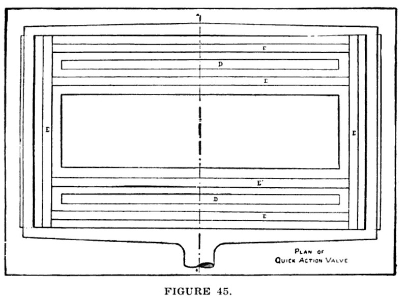
In the plan view (Fig. 45) the relative position of the side bars and the end bars E to each other is clearly shown.
The valve is also shown to have an open back, which prevents the exhaust steam from having any effect upon the valve, but allows it to keep the bottom of the cover well lubricated.
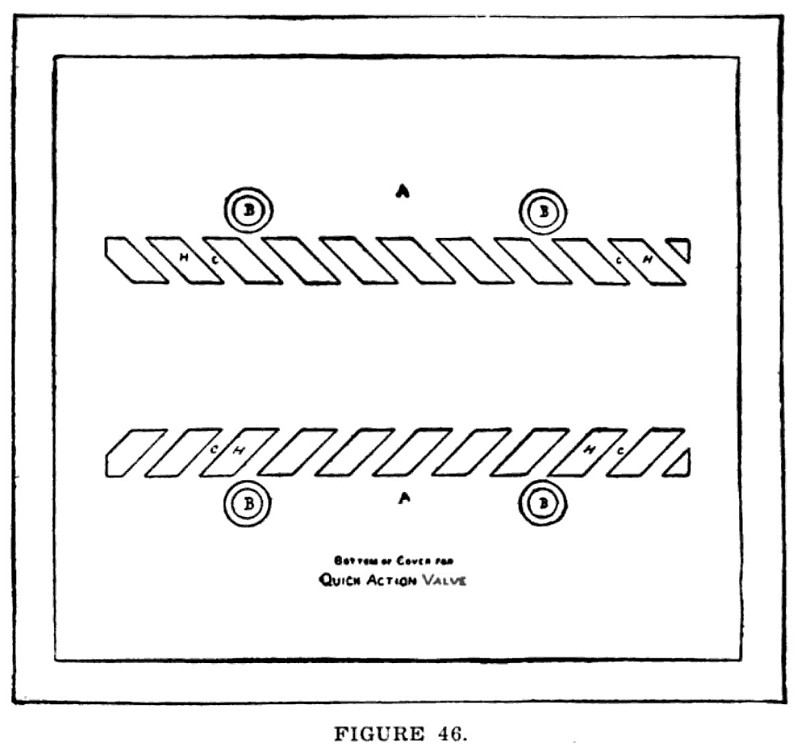
Fig. 46 shows a view of the bottom of the cover A. The ports H, are shown placed diagonally with the small bars C, in them.
The reason that ports H are placed diagonally is to prevent ridges from becoming worn on the packing bars E as they move across ports H.
US Patent: 912,372
https://www.datamp.org/patents/displayPatent.php?number=912372&typeCode=0 |
|
 1908 Article-Gould Balance Valve Co.-Gould Quick Action Valve
 1908 Article-Gould Balance Valve Co.-Gould Quick Action Valve
 1908 Article-Gould Balance Valve Co.-Gould Quick Action Valve
|
|