|
Title: |
1918 Article-Morris Improved Beading Tool Co., Morris Tube Beader |
|
Source: |
Power, V47, #4, 22 Jan. 1918, pg 122 |
|
Insert Date: |
1/4/2024 7:32:58 PM |
Morris Improved Tube Beader
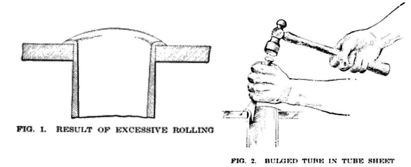
To properly expand and bead a boiler tube requires considerable experience and expertness when the common expander and beading tool are employed. An inexperienced workman is more than likely to thin the tube end by excessive rolling, as in Fig. 1, thus reducing its strength where it is needed. In beading the tube ends by the hand tool may be bulged, as shown in Fig. 2, thus forming a pocket between the tube and the tube head, which would increase the possibility of the tube burning out at that point.
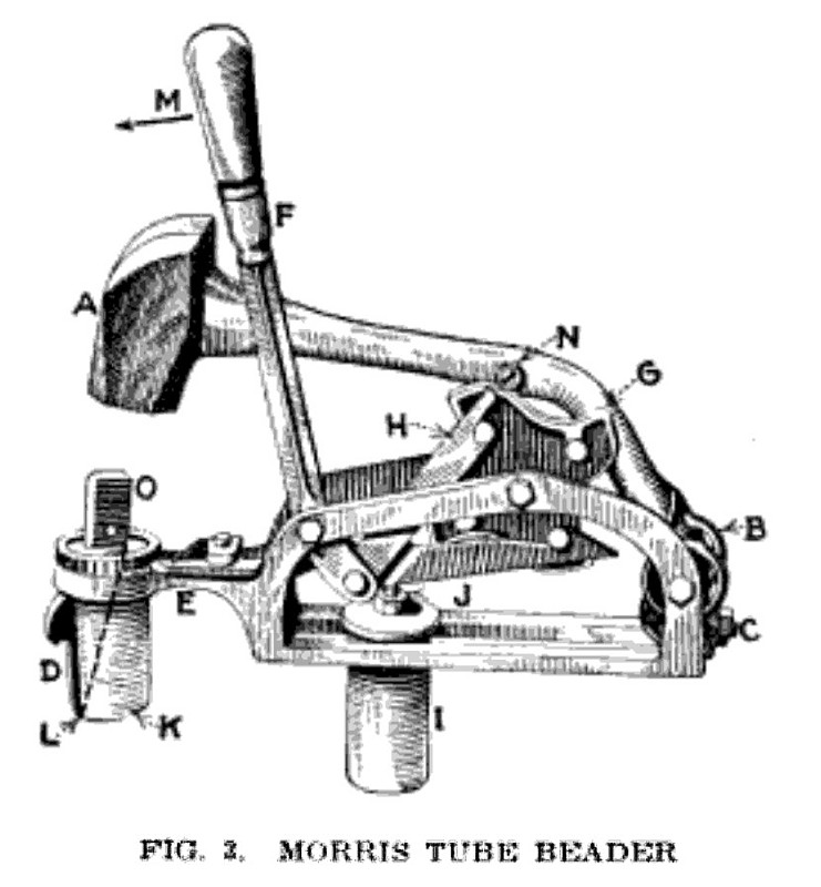
A machine that has been designed to strike a blow on the beading tool at the right position and to expand and bead a boiler tube at one operation, at the same time eliminating the defective results shown in Figs. 1 and 2, has been developed by the Wallace Manufacturing Co., 1319 West 42nd St., Kansas City, Mo. This device, Fig. 3, known as the Morris beading tool, consists of a lever-operated 6-lb. hammer A, the striking blow of which is governed by the propelling springs B, the strength of which is adjustable by the bolt C.
A beading tool D, which beads and expands a tube in one operation, is at one end of the frame holding the hammer. It is rotated in the tube by a ratchet movement E actuated by the hand lever F which operates a camwheel G which is rotated by the two pawls H to lift the hammer and trip it into action. The tool is held in place at a boiler head by an adjustable supporting block, I, containing wedge bolts, which are expanded after the supporting block is placed in a tube, by the bolt J. A head block K holds and guides the beading tool in place, and the dotted line L shows the angle the tool is driven on for expansion of the tube.
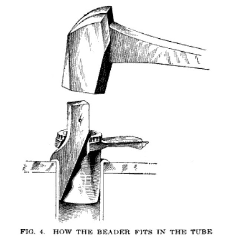
The application and operation of the tool are simple and it can as easily be worked at one part of the tube sheet as at another. When about to use, the head block of the beading tool is placed in the tube to be secured in the tube sheet. the supporting block being placed in any other tube already in place, within the scope of the tool. With the tool in place the operator pulls or pushes the lever in the direction of the arrow M. This movement rotates the cam-wheel G to the right, and as the roller N reaches the edge of the cam-wheel, the weight of the hammer A and the tension of the springs, B produce a sharp blow on the head block O. Each time the lever is operated for a hammer stroke, the ratchet is rotated two notches. Fig. 4 shows how the beader enters a tube and also the kind of joint it produces between the tube and the head, there being no thinning of the tube end or forming of a pocket between the tube and the head.
US Patent: 1,162,871
https://datamp.org/patents/displayPatent.php?number=1162871&typeCode=0 |
|
 1918 Morris Improved Beading Tool Co., Morris Tube Beader
 1918 Morris Improved Beading Tool Co., Morris Tube Beader
 1918 Morris Improved Beading Tool Co., Morris Tube Beader
|
|