|
Title: |
1866 Article-Cool, Ferguson & Co., Thompson's Patent Barrel Making Machines |
|
Source: |
Scientific American, V15, 17 Nov., 1866, pg. 331 |
|
Insert Date: |
9/4/2023 10:37:44 PM |
Improved Patent Barrel Machinery.
The development of the petroleum interest has given an extraordinary impetus to the manufacture of barrels and stimulated and directed invention to the improvement of machinery for rapidly turning out suitable vessels for the reception of the liquid wealth. Our vast commissariat operations also, rendered necessary by the war, added to this demand. In consequence of these events, large manufactories for the production of barrels and casks have been started all over the country, which, by means of improved machinery, have revolutionized the art of the cooper. The slow hand processes by which barrels were heretofore produced have given place to the rapid results of labor-saving machinery. The illustrations we, herewith present, show machines which exhibit much ingenuity and appear to be well adapted to the purposes designed. The engravings represent three machines, intended to do most of the work required in preparing stock for the manufacture of barrels. These machines are intended to finish completely both staves and head.
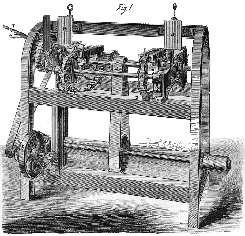
Fig. 1 is a perspective view of a machine for sawing staves to a uniform length, crozing their inner ends for the reception of the barrel head, and chamfering the end edges—all of which are performed at one operation. The shaft, and pulleys, A, give motion to the counter shaft and pulleys, B, and these again to the feed pulley, C. They also drive the saw and cutter shaft by means of the belt, D. Two shafts, one on each side of the saw shaft, carry wheels, over which move chains, which have side projections, guiding them exactly in line through the longitudinal slots of the fixed bars, E. Vertical lugs are attached to the chains at equal distances, which give a horizontal motion to the staves as they are fed on the chains.
As they come under the operation of the saws, F, and the chamfer cutters, G, with the V-shaped crozing cutters, they are held firmly by the adjustable plates, H, and the corresponding under plates, which bear upon springs, that allow, by yielding, for the varying thickness of the staves. The feed pulley, C, turns free on its shaft, and is connected or disconnected by means of a clutch, the handle shown at I.
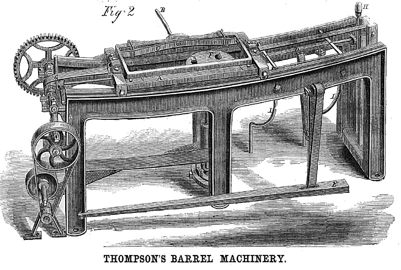
Fig. 2 shows the stave-jointing machine. The top of the frame is concave, corresponding with the bilge of a cask, and on it travels longitudinally a carriage, A, gibbed to the frame slides, but moving freely. Secured to this carriage by pivots at each end, is a receiver, which holds the staves, placed edgewise, by means of the cam lever, B, operating on a spring, C. At D is a movable framed platform, pivoted to one side of means of the strap and the frame, and raised by treadle, E. The staves are placed, edge up, on this movable platform, when the carriage is over it, and clamped by the cam lever, B, into the carriage. At F, in the center of the machine, is a horizontal cutter head driven by a vertical shaft, which joints the staves, the bilge being given by the concavity of the slides, and the bevel by the position of the carriage which holds them.
A strap attached to this carriage winds on a roller, G, which, by its revolutions, draws the carriage with its load of staves regularly and gradually over the cutter head, F. A weight attached to the other end of the carriage draws it back when the jointing is performed, by means of the release of the roller, G, which is connected to the shaft on which it is placed by a clutch. This clutch is operated at this end by a latch on the carriage, and at the other end by the lever, H, through the intervention of a horizontal shaft inside the frame. Arrived at the other end, the receiver in the carriage, A, is reversed, so that the lever, B, is on the other side. The platform, D, being brought up by the treadle, E, levels the staves by their finished edges, and the operation is repeated, the staves when finished sliding to the floor on the guides, I.
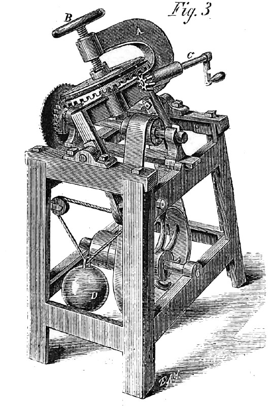
Fig. 3 represents the heading machine, which saws and chamfer’s the head at the same time. The cutters are a concave or dish saw, and a cutter head, secured on the same shaft. A is a U-shaped yoke, having a gear secured to a stud working in the lower half of the yoke. The back or top of this gear is a plane surface, and on it are placed the boards intended to form the barrel head. Directly over this secured loosely to the gear is a circular clamp screw, worked by the hand-wheel, B, so that the clamp will rotate with the gear, which is driven by the shaft and pinion, C, The yoke is pivoted to the frame, allowing it to assume either an upright or inclined position. A weight, D, attached to the lower part of the yoke, brings it to an upright position when the pressure is removed. When the board, or boards, are secured between the clamps, the yoke is inclined to the saw and cutter, and the head rotated by the crank, C, or by power, the concave saw chamfering one edge and the cutter head the other. By means of adjusting bolts the saws can be moved laterally, and the yoke elevated or depressed to saw heads of an required diameter.
These machines were patented August 8,1865, For additional facts address J. S. Thompson, Glen’s Falls, N.Y.
US Patent: 44,233
https://datamp.org/patents/displayPatent.php?number=44233&typeCode=0
US Patent: 49,320
https://datamp.org/patents/displayPatent.php?number=49320&typeCode=0
US Patent: 52,772
https://datamp.org/patents/displayPatent.php?number=52772&typeCode=0 |
|
 1866 Cool, Ferguson & Co.-Thompson's Stave Sawing Machine
 1866 Cool, Ferguson & Co.-Thompson's Stave Jointing Machine
 1866 Cool, Ferguson & Co.-Thompson's Barrel Heading Machine
|
|