|
Title: |
1911 Article-Hamilton Machine Tool Co.-Relieving Lathe |
|
Source: |
American Engineer and Railroad Journal, V85, Nov., 1911, pg. 444 |
|
Insert Date: |
2/7/2023 7:40:07 PM |
One of the most progressive steps in lathe manufacture that has occurred in many years is noted in the new "Hamilton” relieving lathe which is the latest production of the Hamilton Machine Tool Co. of Hamilton. O. This new machine is a lathe with a relieving device for backing off straight or taper taps or reamers, also for both straight, angular and face mills. The novelty of this construction is that it will not only do the work of any lathe, but will do the work of any relieving machine as well.
The attempt has been made in the past to provide this dual capacity through relieving attachments, but these cannot be likened to other than makeshifts, as through their use only straight work is possible, whereas in the machine under consideration taper, angular and face work can be performed with equal facility. This relieving device is not an attachment in any sense, but is built into and is a part of the lathe itself. At the same time the interchange of a long screw for a short one throws out the relieving feature of the machine and converts it into a standard lathe. The new machine will relieve all straight and taper tap and reamers, also all straight and angular face mills up to 10 in. in diameter, with any number of teeth from two to sixteen. It is not confined to outside relieving, but will do inside work as well, such as hollow mills, doing it as rapidly and as accurately as a machine built solely for that purpose.
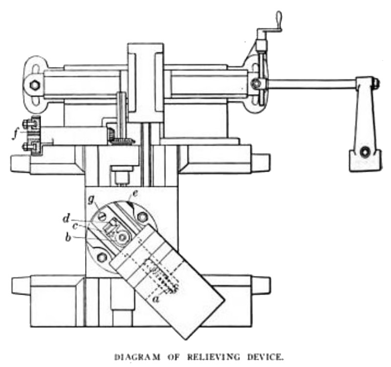
An analysis of the relieving device becomes naturally the most interesting feature in the study of this fine tool, and through reference to the line drawing of the top of the carriage its operation may be readily grasped.
In this a is a coiled spring adjusted by means of a screwdriver screw and is provided with a lock nut, which should be kept tight so as to maintain an even pressure of the cam link c against the cam b. Of the latter three are furnished, one double, one triple, and one quadruple, which arc sufficient for relieving sixteen numbers of teeth, from 2 to 16 inclusive. This cam is easily removed after releasing the tension of spring a, and it is held in place by a screw and washer, c is the cam link, which is held against the cam b by means of spring u, and must be removed before trying to lift out cam b.
The adjusting block, which gives any amount of relief from 1/32 in. to 5/16 in. is marked d, and is operated by the adjusting screw e. This is a double screw, one inside of the other, and by loosening the outer screw and turning the inner screw, either to the right or left, the amount of relief is increased nr diminished as required. f is the adjusting gear and is used for setting the work in proper relation to the tool so that the same will "kick back” at the proper time. This is a very handy feature, as by loosening the two bolts the spindle can be turned by hand without changing the position of the cam. g is a short screw, and when the lathe is not required for relieving should be removed and the long screw which is furnished put in its place. This substitution converts the machine into a standard lathe.
The new lathe will handle work up to its greatest capacity between centers, the relieving mechanism being driven from the back gearing through change gears and a splined rod which extends the* full length of the bed. The shaft drives a spur gear, which in turn drives another spur gear running loose on a slotted disc which is keyed to a bevel gear shaft. Changing the throw to suit any particular work is accomplished by turning a screw on the outside of the swivel. This regulates the position of the adjusting block that slides along the cam link inside of the swivel and connects with the cam. The swivel itself, turning easily on its center post, enables the tool to be brought up to the work from any position desired. The compound rest tool slide is held up against the cam by a heavy adjustable spiral spring, which assures positive action and reduces the possibility of looseness through wear to a minimum. All shafts on the carriage run in hardened and ground bearings and are provided with hardened and ground thrust washers. |
|
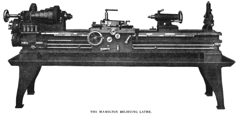 1911 Hamilton Machine Tool Co.-Relieving Lathe
 1911 Hamilton Machine Tool Co.-Relieving Lathe Diagram
|
|