|
Title: |
1885 Article-James Archdale & Co., Heavy Metal Shaper |
|
Source: |
Mechanics' Magazine, V7, Jul., 1885, pg. 207 |
|
Insert Date: |
5/7/2022 9:56:42 PM |
|
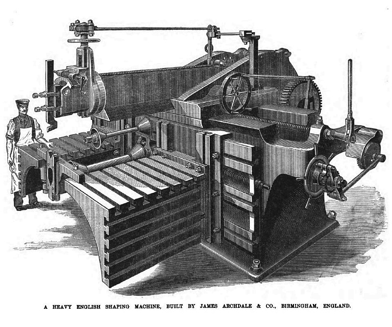
The engraving shown herewith, reproduced from a recent issue of the Engineer, Illustrates an unusually large shaping machine turned out by the British firm, Messrs. James Archdale & Co., of Birmingham. The length of stroke of the machine is 3 feet, the longitudinal traverse of the saddle, 9 feet and the length of the bed, 12 feet. The total length of the bed over the bracket at end is 18 feet; the tables project 4 feet, 3 inches; the vertical movement of the tables is 18 inches, and the power of the gearing is 12 to 1 and 20 to 1. There is a quick return stroke. There are cast-steel link connecting-rods and feed-wheels. The tables are constructed to sustain a weight of 12 to 15 tons. The machine is self-acting in all cuts and has two circular motions for large and small work. The total weight is 24 tons and the ground space taken up measures 20 x 18 feet. The main frame of the machine is cast in one piece and strongly ribbed inside. The foot of the frame is extended to the left, to support the driving gear. The weight of this frame is 11 tons. The driving gear, &c., consists of a five-speed cone pulley from 20 to 36 inches in diameter and two changes of spur gear. The changes are effected by a screw on the pulley-shaft, the boss of the hand-wheel being cut as a unit internally and split, and provided on its outer diameter with a split grip for locking. By moving this hand-wheel the pinions can be brought in and out of gear with their respective wheels and locked in position on the shaft. These wheels give motion to a strong back-shaft having a key bed and sliding pinion carried in a bracket at the back of the traveling-head or saddle. This bracket and saddle are all one casting. The pinion works into a powerful spur-wheel keyed fast on the main crankshaft, also carried in a bearing at back of saddle. The saddle or traveling-head weighs 3 tons and has carried from it at the back and hanging downward, two strong brackets for support of the main gear. The crank is variable and the sliding block is moved in the crank plate by a rack and pinion and is fastened in desired place by two lock-nuts. This crank actuates a cast-steel link and connecting rod and gives a quick-return stroke, the connecting rod being inside the ram, thus giving a central thrust. The saddle is self-acting either way along the bed by a slotted disk, connecting-rod catch and cast-steel wheels, the screw being locked and stationary, the nut—having a spur-wheel on a friction cone—turning in a bearing cast on the saddle underneath and thus moving the saddle. When it is desired to move the saddle along more quickly, the screw is unlocked at each end of the bed and a ratchet or handle applied to one end and moved direct. The ram is 13 feet, 6 inches long and 2 tons in weight and has a quadrant tool-box for shaping internal or external curves. It also has a noiseless and improved self-acting down-cutting motion. The ram is moved forward or back when being adjusted to the requisite stroke by a pinion working into the rack. There are, as we have said, two circular motions, with minimum feeds of 1/1200 and 1/2400 revolution respectively. The smaller one will take about 24 inches diameter and the larger one, about 48 inches. It is supplied with suitable mandrels and cones and also, a steady bracket supported on both tables. The two tables weigh about 3 tons each and project 4 feet, 3 inches from the bed of the machine and are moved longitudinally by means of screws and vertically by powerful worm-wheels and, worm and screw. |
|
 1885 James Archdale & Co., Heavy Metal Shaper
|
|