|
Title: |
1892 Article-Henley Machine Tool Works- Sixty-Inch Pulley Lathe |
|
Source: |
-Age of Steel, V72, 02 Jul., 1892, pg. 3 |
|
Insert Date: |
10/21/2020 1:57:25 PM |
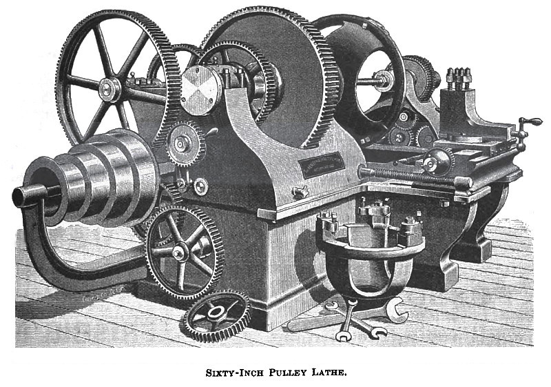
Sixty-Inch Pulley Lathe.
The lathe shown in the accompanying illustration is manufactured by the Henley Machine Tool Works, of Richmond, Ind, and is designed for simultaneously boring and turning pulleys, either straight or crowning face, cone pulleys, gear blanks, and, in fact, a variety of other work may be done with them, especially turning and boring gear blanks for electric motors. The demand for a first-class lathe for turning and boring pulleys at the same time has led to the perfection of this tool, and in its construction none but the very best material and workmanship are employed.
The bed is 10” 4" long, 36" wide at the ends, and 7” 2" wide at the center. The center projections which carry the rails on either side are each supported by two heavy brackets, cast solid to the shelf above. The main spindle is of best steel, 5 15/16" diameter and 45 7/8 long, with a heavy collar forged on, 4" from front end. The nose has heavy threads cut, to receive either of the two chucks furnished, one of which takes pulleys from 60 down to 48", the other from 48" down to 24", or a heavy face plate if wanted, for work which could be held on it.
The front bearing of spindle is 16", and the back bearing 8" long. The bull gear is 36" diameter, face, 3 pitch. The two main pinions are of steel, and these, as well as all other gears on this machine, are cut from solid blanks. The bull pinion on back shaft has keyed on it a large gear to mesh with one of same size on main spindle. This is for use in getting a faster speed for tracing up pulleys and other work. The pinion and gear referred to are arranged to slide on a long feather, and may be thrown entirely out of gear if desired.
A shaft passes through the head stock, parallel with main spindle; on one end is fitted a large disc or friction plate. This shaft is driven by means of intermediate gear from large gear on back shaft. On a level at right angles to this shaft, and through bearing near the front end of head stock, is a shaft extending the full width of the bed, and journaled at ends in bearings, bolted on bed, and has a worm thread extending from the ends to head stock, for driving worm wheels on rail screws. This worm shaft between bearings in head stock is splined and fitted with a fiber friction to regulate the feed of tools. The feed may be varied from 0 to 3/4. The friction plate is thrown forward and brought in contact with fiber friction by means of a T-shaped lever, operated on by a knurl screw passing through e bead stock within easy reach of operator, he rails on either side are 42)4" long and 12)4" W1(*0, The front one is fitted with a saddle and compound tool rest; the ether is fitted with plain saddle and rest. The rail screws are provided at head stock end with a worm wheel friction and hand knurl, which is tightened or released to either start or stop the feed. The bed at each end of rails is graduated to facilitate setting for straight or crowning work.
The foot stock is provided with a boring arbor 3 15/16" by 40" long, threaded about one-half its length with square thread for feed gear, and splined the same distance to receive feather in driving gear, and has four changes of speed for boring holes up to 8" in diameter, and is driven direct from cone pinion through idlers on a sector tumbler. A gear is mounted on this shaft between brackets on foot stock and provided with a feather which works in spline and shaft.
On a shaft below and parallel to boring arbor, extending through a sleeve in foot stock, and provided on the outer end with a hand wheel and knurl, is a female friction gear made fast to the inner end of this shaft and meshes with the feed gear on boring arbor. Between this gear and the bearing is located a male friction gear mounted loosely on said shaft, meshing with driving gear on arbor. On the end of sleeve through which this shaft passes, is mounted a tumbler to which is secured an idler gear meshing with male friction gear. By means of a lever this idler is thrown in gear with gear on lower shaft, and the boring arbor put in motion. To start the feed on boring arbor, the hand knurl is tightened, which brings the two| friction gears together.
The arbor is bored taper to receive boring bar gland. The boring bar, which is 1 7/8”x43", is provided with one flat cutter and will bore 16" deep. The foot stock may be moved along the bed either to or from the work. The lathe is geared 75 to 1, has driving cone of four steps, 19, 16,13 and 10"x 4 1/2" face. Weight, 13,000 pounds. All sliding surfaces are scraped to true bearings, and all bolts, nuts and screws subject to wear are case-hardened.
On account of the weight of foot stock of 60-inch lathe, power mechanism is employed for moving it. Valuable improvements have recently been made on these machines, rendering them as efficient for purposes designed as it is possible to make them. They are built in a very solid and substantial manner, symmetrical in proportion, and of the very best construction and finish. The power and capacity of these machines, and speed in performing their work in an accurate manner, and above all, the advantages (possessed by no other machines) of boring and turning simultaneously, requiring but one man to operate them, gives them first place among the best class of time and labor-saving machinery. For further particulars, address the manufacturers. |
|
 1892 Henley Machine Tool Works- Sixty-Inch Pulley Lathe
|
|