|
Title: |
1911 Article-Bradford Machine Tool Co., Lathe Carriage with Taper Attachment |
|
Source: |
Machine Tools Commonly Employed In Modern Engineering Workshop, V1, 1911, pgs. 41-43 |
|
Insert Date: |
5/25/2020 7:47:43 PM |
|
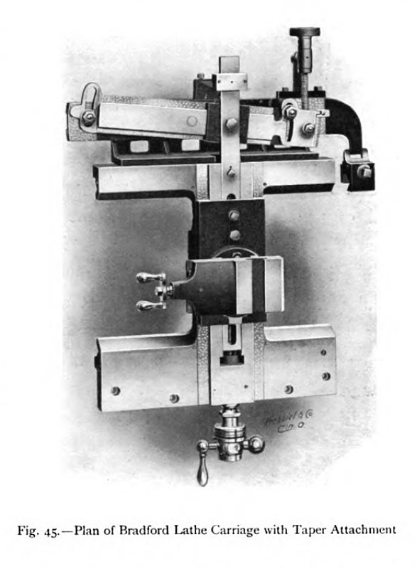
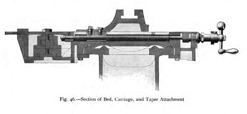
For tapers of considerable angle, a special taper-turning attachment is very frequently supplied. One of these devices as applied to a Bradford lathe is illustrated in fig. 45, which is a general view of the attachment viewed from above, and in fig. 46, which is a section through the attachment mounted upon the bed of the lathe. With an arrangement of this kind it is not necessary to displace the tailstock centre, and the work, therefore, rotates about an axis parallel to the bed, as in the case of ordinary parallel work. To form the required taper, the tool is moved transversely as it travels along the bed; the amount of the transverse motion being determined by the inclination of the adjustable slide, shown at the rear end of the attachment. This slide is adjustably mounted on a lower slide which is movable in a direction parallel to the length of the bed. On the upper slide is mounted a movable shoe, to which is pivoted the bar that moves the slide rest transversely across the carriage. From an examination of the illustrations it will be evident that, if the carriage is moved in the longitudinal direction relatively to the slide-bar at the rear end of the attachment, the slide-rest carrying the tool will be moved to or from the work by an amount depending on the inclination of the upper adjustable slide, which thus deter- mines the amount of the taper. Scales, engraved in degrees of taper angle and in inches of taper per foot of length, are provided at the two ends of the adjustable slide, which can thus be readily set to produce the taper required. To obtain the required movement of the parts, the rear slide is anchored to the bed of the lathe by means of the clamping dog, shown at the extreme right-hand side of the general view. Thus, while the saddle moves along the bed. the adjust- able slide remains stationary; and the consequent relative motion of these parts results in a transverse movement of the tool-rest. It will be seen from the section that the tool-rest is connected to the driving bar through the intermediary of the screw and nut, by means of which the tool-rest is ordinarily operated by hand or power. As the driving bar moves in its guides it carries with it the screw and nut to which the lower slide of the tool-rest is connected by means of the square-headed clamping bolt shown in the section. The outer end of the screw is splined and telescopes into the operating handle sleeve, which also carries the power-feed pinion. Rotation of the handle thus moves the tool-rest independently of the taper-adjustment driving bar. To put the attachment out of action, all that is necessary is to loosen the clamping dog from the lathe bed; and, since the attachment is completely self contained, it is possible to turn taper portions on any portion of the length of the work by moving the attachment to the required position on the bed. A device of the nature described can be arranged to turn on the work other profiles than straight tapers by giving the adjustable slide a curved form, such as would be required, for example, to form the curved point of a projectile. |
|
 1911 Bradford Machine Tool Co., Lathe Carriage with Taper Attachment
 1911 Bradford Machine Tool Co., Lathe Carriage & Tool Rest (Cross Section)
|
|