|
Title: |
1911 Article-D. & J. Tullis, #6 Vertical Drill Press |
|
Source: |
Machine Tools Commonly Employed In Modern Engineering Workshop, V2, 1911, pgs. 13-15 |
|
Insert Date: |
4/14/2020 7:28:19 PM |
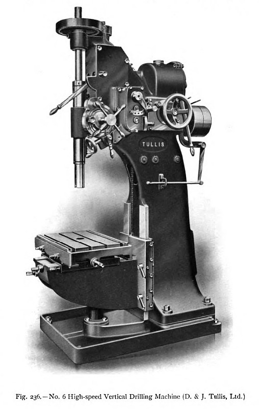
A powerful type of vertical drilling machine, in which a strong box section frame is substituted for the column of the machines hitherto described, is illustrated in fig. 236. This machine, manufactured by D. & J. Tullis, Ltd., of Clydebank, is specially designed for the effective use of high- speed steel drills; but suitable speeds are also provided for the use of ordinary carbon-steel drills, and for boring operations with bar and cutter. Efficient lubrication of the working parts, and particularly of the spindle, is necessary in any machine intended for the use of high-speed steels; and in this machine particular attention has been paid to the lubricating arrangements, all the bearings being- bushed, and fitted where necessary with ring oilers.
The machine illustrated admits work of 36 in. maximum diameter. Its body consists of a box casting of ample section sufficiently strong to withstand severe stresses and to absorb vibration, and the body is rigidly bolted to a large base plate, flanged to hold the cuttings and oil. Upon the strong knee bracket which works on the machined face of the body, is mounted a compound table, having a traverse of 11 in, longitudinally and 21 in. transversely. All the guides are of the square type, fitted with taper strips for the adjustment of wear, and suitable locking arrangements are provided in all cases to prevent the parts from yielding. The knee bracket is raised and lowered by means of a telescopic screw, operated by a handle at the front, and there is no danger of the knee being forced downwards during heavy drilling operations, as is sometimes the case when the table is raised by rack-and-pinion gear and is then merely clamped in its position.
The crucible-steel spindle runs in a long cast-iron sleeve, which is fitted with a steel rack providing a traverse of 15 in. By operating the hand lever, projecting conveniently from the front of the machine, the spindle can be stopped, started, or reversed instantly, through the intermediary of a double clutch. A ball bearing is provided to take the thrust of the spindle, and lock nuts are fitted for taking up wear. Six changes of feed, ranging from 24 to 120 cuts per inch, can be obtained at any moment, while the spindle is running, by suitably manipulating the handles of feed-box, and all the gears are enclosed and run in oil. When the lower feed handle is placed in its mid position, the spindle can be fed by hand, by means of the small handwheel on the front end of the inclined worm shaft. Provision is also made for disengaging the feeds, and for racking the spindle rapidly up or down by hand. There is provided, in conjunction with the feed gear, an automatic trip motion and depth indicator, which disengages the feed when the desired depth has been reached, and releases the spindle, which can then be quickly returned by hand. As in the case of the feed-box, the gears and clutches of the spindle change-speed box are entirely enclosed and run in oil. There are twelve changes of speed, ranging from 17 to 400 revolutions per minute, the changes being obtained by placing the handwheel and lever in the various relative positions, indicated on the speed table attached to the side of the machine. It will be seen from fig. 236 that the belt-shipper handle is placed in a convenient position at the side of the column. |
|
 1911 D. & J. Tullis, #6 Vertical Drill Press
|
|