|
Title: |
1911 Article-John H. Storey & Co., Geared & Turret Head Vertical Drills |
|
Source: |
Machine Tools Commonly Employed In Modern Engineering Workshop, V2, 1911, pgs. 4-9 |
|
Insert Date: |
4/9/2020 10:43:16 PM |
An interesting arrangement, in which the drill is rotated and the work is fed up to it, is illustrated in fig. 227. This machine, built by Messrs. John H. Storey & Co., of London, is provided with a turret head, upon which a variety of drill or other tools can be mounted and thus a piece of work can be drilled, bored and tapped completely at one handling of the piece. It will be seen that the table is raised and lowered by a hand rack-and-pinion gear, the table being balanced by the counterweight, shown at the side of the machine. The various spindles of the turret head are driven by bevel gears, which engage a bevel wheel on the cone-pulley shaft, shown at the top of the machine.
Two drilling machines, by the same makers, are illustrated in figs. 228 and 229, the former being arranged to drill to the centre of a piece of 22 in. diameter, and the latter to the centre of a piece of 36 in. diameter; that is, the clear distance from the spindle centre to the machine column is 11 in. in the former and 18 in. in the latter. Owing to the overhung arrangement of the spindle in all drilling machines of this type, the column of the machine is subjected to bending forces which vary with the power of the drill and with the overhang of the spindle beyond the column, and to ensure accurate work it is necessary that the column should be strong and well designed to withstand the bending forces to which it is subjected. When the bending forces are considerable the single-column construction, adopted in the case of the 22 in. machine illustrated in fig. 228, is strengthened by means of a back frame, shown in fig. 229, the frame being arranged in the plane of the spindle and the main column. The column and frame together thus form a deep girder, well suited to resist considerable bending forces. As both the range and the power of the large machine are greater than those of the smaller one, all the parts of the former are of a stronger construction to withstand the heavier requirements, and although the two machines have not exactly the same construction, a description of the larger machine will suffice also for the smaller The work to be drilled is mounted upon a table, which can be raised or lowered by a rack-and-pinion gear, and the table is capable of rotation so that by suitably arranging the piece a series of holes may be drilled, for example, around the flange of a valve without resetting the piece and by merely rotating the table. Large work, not suitable for mounting on the table, can be set up on the extended bed, the table being so arranged that it can be swung aside clear of the work. Around the base there is formed a trough, which serves to collect the oil used in the drilling operations. Upon the machined face, on the front of the column, is gibbed the sliding head, which carries the spindle sleeve. This sleeve is led up and down by a rack-and-pinion gear, operated either directly by hand or through a worm and worm wheel, shown at the side of the head. The worm can be driven by means of the handwheel at the front end of the worm shaft, or power-driven through the bevel gears at the rear end, the power drive being engaged or disengaged, as required, by means of the push at the centre of the handwheel. The splined shaft of the power bevel wheels, the keys of which work in the keyway of the spindle. These bevel wheels can be raised or lowered together, so as to bring one or other into mesh with the driving bevel pinion by means of the long hand-lever at the front of the machine, and thus the direction of rotation of the drill spindle can be immediately reversed when, for example, feed bevel gear is driven by cone gears from a pinion on the spindle, but in the illustration these gears are hidden by their protecting covers. By means of the projecting knob the gears can be clutched and various feeds obtained. When it is desired to operate the spindle sleeve quickly by hand, the worm can be dropped out of gear with the wheel, and a trip gear is also provided for automatically disengaging the feed when the drill reaches the desired depth. From the hammered-steel drilling spindle the thrust is communicated to the sleeve through a ball thrust, which considerably reduces the frictional resistance. The upper portion of the spindle is splined, and at the top it passes through two it is desired to withdraw a tap or a stud. The bevel driving pinion is driven from the step cone through double back gearing, operated by the hand lever at the side of the machine. At a lower level on the same side of the column will be seen the hand lever for shipping the driving belt. Weights within the column are provided for balancing the sliding head and the spindle. |
|
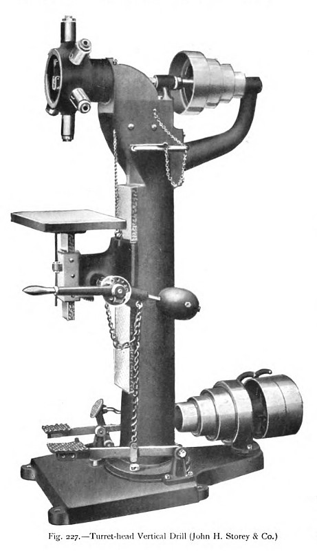 1911 John H. Storey & Co., Turret Head Vertical Drill
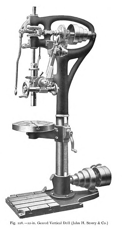 1911 John H. Storey & Co., 22" Geared Vertical Drill
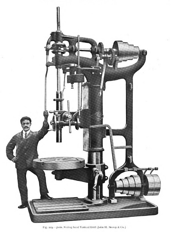 1911 John H. Storey & Co., 30" Sliding-Head Vertical Drill
|
|