|
Title: |
1911 Article-Dean, Smith & Grace, 20 & 28 in. Centre Lathe |
|
Source: |
Machine Tools Commonly Employed In Modern Engineering Workshop, V1, 1911, pg. 29 |
|
Insert Date: |
3/30/2020 11:39:20 AM |
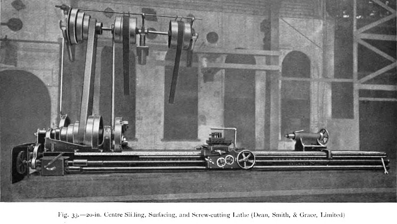
A large and powerful, high-speed, sliding, surfacing, and screw-cutting lathe, constructed by Messrs. Dean, Smith, & Grace, Limited, of Keighley, is illustrated in fig. 33. In this machine the height of the spindle centre above the bed is 20 in., and over the saddle 14½ in. Between the head- and tailstock centres the available length is 8 ft. 9 in. in the example illustrated, but other lengths can be provided. The lathe is therefore well adapted for the manufacture of long screws, and for the turning of long spindles and shafts. Two speeds, namely 150 and 118 revolutions per minute, are provided by the special arrangement of overhead countershaft, and the spindle-cone pulley has five steps, ranging from 16 to 44 in. in diameter, the width of belt being 7¼ in. A notable feature of the overhead counter gear is the simple means adopted for relieving the tension of the belts when they are running idly on the loose pulleys. This is effected by making the diameters of the loose pulleys slightly less than those of the fast pulleys, and by tapering the intermediate edges so that the belt glides easily from the one pulley to the other. The lathe head is provided with a back gear of 13.3 to 1 ratio, and the spindle speeds obtainable range from 3.3 to 412 revolutions per minute. Feeds of 4, 8, and 16 cuts can at once be obtained by operating the lever on the front of the gear box. In general, the design of the parts of this lathe does not differ essentially, except as regards size and weight, from that of the 12 in. centre lathe by the same makers, already fully described.
A still heavier lathe, designed for dealing with crank shafts—one of which is shown in position between the centres—and for similar heavy work, is illustrated in fig. 34. Notwithstanding the size of the machine it is possible for one man to supervise efficiently its operation, as the controlling levers are grouped in convenient positions. From the bed to the spindle centre the height is 28 in., and over the saddle the clear distance is 21 in. As in the previous example, the overhead gear provides two speeds, but the cone has four steps. In addition, the head is treble-geared, so that ample power is obtainable for all requirements, and the range of speeds is considerable, ranging from 2.1 to 82.5. The bed is of box section and has large wearing surfaces with square guiding edges. Two toolboxes are mounted upon the saddle, which can be controlled from either side. These toolboxes are of solid construction and have no overhang, thus obviating any springing tendency of the tools. Positive self-acting feeds are obtained by means of gears contained in the box at the end of the bed, or underneath the headstock when the height of the centres is sufficiently increased. The feeds are controlled by levers, which indicate, at the same time, the amount of traverse the operator is using. There are two quadrants or re verse plates operated by worm gear and hand wheel. By these means the sliding and surfacing motions may be reversed in either direction and independently of one another. For the surfacing motion there is provided the splined driving shaft, shown at the front of the bed. For sliding work the carriage is moved by means of a 5 in. diameter screw of 1 in. pitch, which is carried along the centre of the whole working length of the bed. |
|
 1911 Dean, Smith & Grace, 20 in. Centre Lathe
 1911 Dean, Smith & Grace, 28 in. Centre Lathe
|
|