|
Title: |
1911 Article-Lodge & Shipley Machine Tool Co., 13½ inch Engine Lathe (Part 1) |
|
Source: |
Machine Tools Commonly Employed In Modern Engineering Workshop, V1, 1911, pgs. 20-21 |
|
Insert Date: |
3/25/2020 4:17:45 PM |
Lodge & Shipley I3½-in. Centre Screw-cutting Lathe.
Of the several interesting features embodied in the engine lathes of the Lodge & Shipley Machine Tool Company, Cincinnati, America, the patent headstock is probably the most noticeable, as will be evident from an examination of fig. 22, which illustrates the application of the head to a 27-in. swing lathe designed for the heavy speeds and feeds now required for the efficient use of modern cutting tools.
The Bed. — Fig. 23 is a top view of the bed and slide rest, showing the rack, drop bridge, and shear wipers, while fig. 24 is a view of the underside. A cross section through the 42-in. apron and a portion of the bed is also given in fig. 25. From the general view of the lathe, and from the various illustrations referred to, it will be seen that the bed is of massive proportions, and that it is carried upon two box pedestals, which make the provision of specially heavy foundations unnecessary. By means of cross girths the bed is strongly braced internally, and the torsional rigidity thus obtained is considerable. From the section, fig. 25, and also from fig. 24, it will be seen that the carrier and tailstock clamps pass over the top of the cross girths, and that no clamping bolts pass through to the underside of the bed. In the case of the tailstock the clamping bolts project from the upper side of the head, where they are readily accessible. For the guidance of the carriage there are provided, along the front and the back edges of the bed, raised inverted V's with the tops well rounded off to prevent bruising. For the guidance of the tailstock, and the support of the fixed head, there is provided at the back of the bed an inside inverted V, and at the front an inside flat surface upon which the carriage also bears, as indicated in fig. 23.
This arrangement, which is common to many modern lathes, permits the projecting portions of the carriage to pass the sides of the fast headstock, and thus enables the tool, mounted over the middle of the carrier, to be brought right up to the spindle head.
All Lodge & Shipley lathes of more than 20-in. swing have, along the centre of their beds, a longitudinal rib or brace of box section, upon the upper surface of which is cast a rack, into which engages a pawl attached to the underside of the tailstock. This rack is clearly shown in fig. 23.
The Carriage and the Apron. — As already mentioned, the carriage is supported along its whole length upon the front and back outer V's, and in addition the front inside fiat surface provides a direct support immediately under the tool. The bridge joining the front and back portions of the carriage is cast deep between the lathe shears; and, as gibs are provided for the removal of slackness, the possibility of appreciable springing of the carriage, when heavy cuts are being taken, is not great. The steel feed rack, by means of which the carriage is moved along the bed, is cut in one length, and is securely attached to a machined recess on the bed immediately under the front V guide. The pinion wheel, which engages with this rack, is carried upon the apron front plate, but the pinion stud, instead of being overhung, as is sometimes the case, is borne at its outer end upon a back plate or bracket, as illustrated in fig. 25.
To prevent the rack and pinion from being forcibly sprung apart when the feeding force is great, the back plate of the apron is supported upon a steel ledge recessed into, and securely attached to, the front wall of the bed in a position practically in line with the direction of thrust between the rack and pinion. From the illustration it will also be seen that the lead screw is placed directly under the front guide of the carriage.
A general view of the gearing carried on the back of the apron plate is given in fig. 26, from which it will be seen that the two halves of the nut, which can be made to engage the lead screw by means of a cam, are carried in stout vertical guides shown at the left side of the illustration. The threads of the lead screw are only in use when the lathe is screw -cutting, the ordinary longitudinal and cross feeds being effected by means of the double -bevel gear sleeve, the long key of which engages with a spline cut in the lead screw. A reverse lever on the front of the apron moves the double-bevel gear so that it meshes on the right or the left, and drives the carriage or the cross feed, as the case may be, in one direction or the other. When the feed is engaged, a finger connected to the reverse lever is automatically inserted in the path of the half-nuts, and thus the danger of the feed and screw-cutting gears being simultaneously engaged is avoided. As a further preventive against disaster, as for example when the carriage is allowed to overrun its travel, both the longitudinal and the cross feeds are operated by independent friction clutches, which slip before the breaking point of any portion of the gear is reached.
Difficulty is often experienced in preventing grit from entering between the working surfaces of the shears and the carriage, and to overcome this trouble shear wipers and oilers are provided at the extremities of the carriage. As the carriage moves along the bed, the dirt is automatically wiped off and the surfaces oiled. A device of this simple nature helps to maintain the truth of the shears and the accuracy of the lathe.
The Tailstock. — Before proceeding to describe the headstock and feed gearing, some reference must be made to certain of the interesting features embodied in the tailstock, which is illustrated in section in fig. 27. Owing to the presence of the cross bracing of the bed, it is not possible to carry the clamping bolts through to the under side, and they are therefore carried upwards, as shown in the illustration, where the bolts are indicated at the top in a very accessible position. To the under side of the base there is hinged a pawl, which engages with the rack on the bed already referred to and prevents the tailstock from backing off when the lathe is doing heavy work, as sometimes occurs when the clamps alone hold the tailstock. To fix the spindle there is provided a cross-plug device operated by the handle near the nose. This split plug grips the spindle and holds it tightly without throwing it out of alignment. As is generally the custom, screws are provided for setting the tailstock transversely for taper work. When the weight of the tailstock is considerable, as is the case in the lathes of over 36-in. swing, a rack-and-pinion drive is fitted to enable the tailstock to be brought readily into position.
The Headstock. — It is claimed for the patent headstock of the Lodge & Shipley lathe that it is free from the defects of the all-geared type of head, and that it possesses several distinctive advantages, more especially in the open-belt speeds that are obtainable with it, for small-diameter work. In the design of the head the requirements that have been considered as being of first importance, in addition to those of reasonable strength and simplicity, are as follows: (a) open-belt speeds should be provided for small diameters and finishing cuts; (6) the spindle bearings, upon which the accuracy of the lathe largely depends, should be relieved of the belt pull; (c) increased force at the cutting tool should be obtained by the use of broader belts, rather than by means of high gear ratios; (d) suitable back - gear roughing speeds on small diameters should be obtainable, and (e) the speed changes should not necessitate the shifting of belts.
A general view of the headstock, with portions of the gear exposed and removed, is illustrated in fig. 28, from which it will be seen that the power is applied through a single wide belt running on a pulley of considerable diameter. Upon one end of the sleeve of this pulley are rigidly mounted the large and the small back driving gears, the latter being shown partially cut away to expose the lathe spindle. On the other end of the sleeve is formed the driving half of the jaw clutch, through which the lathe spindle is driven directly from the driving pulley when the back gears are in the disengaged position, and thus the open-belt speeds are obtained. The driving-pulley sleeve is carried in the two central bearings of the headstock, and the lathe spindle, which passes through the sleeve without being in contact with it, is supported in the outer bearings. In this way the pull of the belt acts on the inner bearings of the pulley sleeve alone, and does not affect the lathe spindle, which runs freely through the sleeve. To provide sufficient force at the tool for heavy cuts a second back-gear ratio of 13.8 to 1 is provided, and in addition, for more moderate cuts beyond the power of the open-belt drive, there is a first back-gear ratio of 3.75 to 1. These back gears are carried upon a rocker shaft mounted on eccentric bushes, which enable them to be swung into or out of mesh with the driving gears as required. The two driven back gears are mounted on one sleeve splined and keyed to the back shaft, so that the gears can be slipped sideways until one or other of the wheels meshes with the corresponding driving gear. Open-belt speeds are thus obtained by swinging the back gear out of mesh and clutching the driving-pulley jaw clutch to the lathe -spindle jaw clutch, which slides on the boss of the spindle face gear. To obtain the high-power low speed the clutch is disengaged, the slip gears are displaced endwise until the small driving wheel is opposite the large driven wheel, and then the gears are swung into mesh. In the same way the intermediate speed is obtained by placing the large diameter driving wheel in mesh with the small driven wheel. When one or other of the back gears is in use, the driving force of the belt is transmitted through the back gears to the back-gear shaft, and thence, through the pinion on the end of the shaft, to the face gear on the lathe spindle.
To obtain a still greater range of speeds, triple back gears are provided, when desired, on the lathes of over 24-in. swing. Three speeds are thus obtainable with the head alone; but, with the special overhead triple gear illustrated in section in fig. 29, nine forward and nine backward speeds are obtainable, or eighteen different forward speeds if both driving pulleys are driven in the one direction at suitable speeds. In the illustration, 2 and 11 are the forward and backward main friction pulleys, one being for the forward and the other for the backward drive; but, as already stated, both may be driven in the same direction at different speeds in order to obtain a greater range. These pulleys are mounted freely on thimbles 3 and 12, which also revolve freely upon the shaft. Efficient lubrication is maintained by filling with grease the chambered spaces within the pulleys and the other revolving portions of the gear.
The engaging friction bands are carried upon sleeves fixed to the shaft 5 by the pins 4 and 8 and the keys 6 and 10. In a similar manner the two friction disks between the bearings of the driven shaft are pinned at 27, 28, 29, and 30, and the outer disk sleeve 22 is pinned at 21 and keyed at 23. The three spur wheels 14, 16, and 18, keyed to the shaft at 15, 17, and 19, are in constant mesh with the corresponding wheels of the clutches on the driven shaft, and the three gear ratios are obtained by moving the friction wedge 26 towards either the left or the right, so as to operate one or other of the two clutches, or by similarly operating the wedge 20 of the third clutch. Either of the two driving pulleys may be clutched to the shaft by moving the friction wedge 7 to one side or the other as the case may be, and thus the forward or backward drive is obtained, or alternatively the two main speeds when the pulleys are driven in the same direction but at different speeds.
Special attention has been paid to the efficient and automatic lubrication of the moving parts, as, owing to the location of overhead gear, the possibility of defective supervision or neglect is always possible.
Screw-cutting and Feed Gears.—To protect the gear wheels from flying chips and dirt, and to secure compactness of design, these parts are mounted between the walls of the bed under the headstock, as illustrated in fig. 30, which is a view of the upper side of the bed with the headstock removed. As the gears in this position are not so accessible as when mounted in external boxes, special provision is made for efficiently lubricating them, so as to avoid the necessity for frequent inspection. The arrangement illustrated is as follows: Upon the splined slip-gear shaft—driven from the spindle through gearing, there is mounted a spur wheel, which can be moved sideways along the shaft key-way by means of the tumbler and knob. Upon the tumbler sleeve, which is carried freely on the shaft, is mounted an idle wheel in con stant mesh with the spur wheel. Upon the lower parallel shaft is rigidly mounted a cone of spur wheels, any one of which may be brought into gear by moving the slip gear into the desired position, as indicated upon the index plate, and then by swinging he idle wheel into mesh. Thus, the motion of the slip-gear shaft is transmitted through the desired gear ratio to the cone-gear shaft, from which it is ultimately communicated to the lead screw. On the outer end of the cone-gear shaft are fixed two gears of different diameters driving two pairs of gears mounted upon the intermediate shaft. The slip gear on the lead screw can be made to engage with any one of the four gears on the intermediate shaft, and thus four times as many speed changes can be obtained as there are gears on the cone shaft, and the changes may be made while the lathe is running. By means of the reverse lever and gears, provided at the end of the slip shaft, the lead may be changed from right to left, and provision is also made upon the plate for the mounting of additional compound gears, with which practically any thread can be cut. |
|
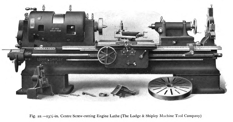 1911 Lodge & Shipley Machine Tool Co., 13½ inch Engine Lathe
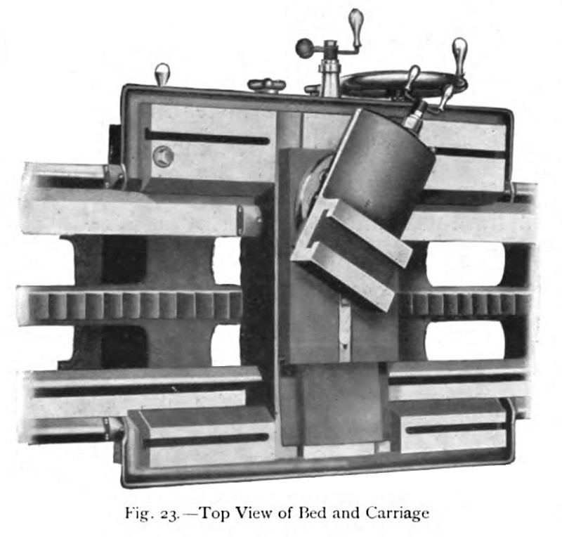 1911 Lodge & Shipley Machine Tool Co., 13½ inch Engine Lathe (Top View of Bed & Carriage
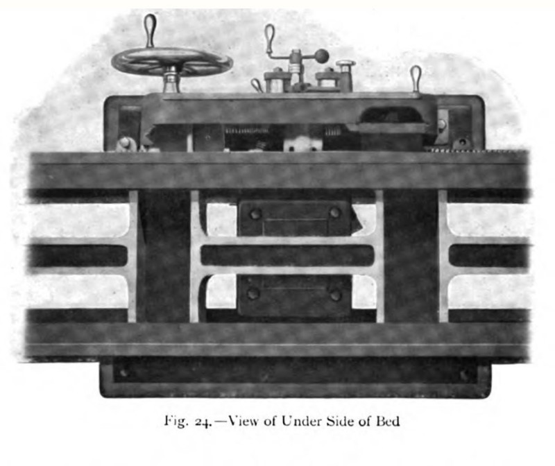 1911 Lodge & Shipley Machine Tool Co., 13½ inch Engine Lathe (View of Underside of Bed
|
|