|
Title: |
1872 Article-Henry J. Dart & Co., Behren's Patent Rotary Engine |
|
Source: |
Elementary Treatise on Natural Philsophy, 1872, pg. 481 |
|
Insert Date: |
12/11/2019 10:00:04 PM |
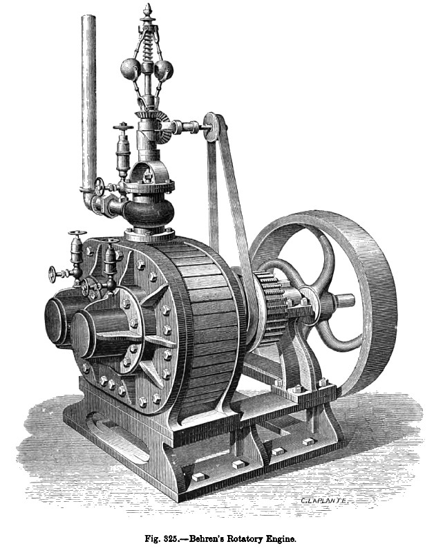
Fig. 325 is a perspective view of the engine, and Fig. 326 a cross-section of the cylinders, showing the mode of action of the steam. C and C’ are two parallel axes, connected outside by two toothed wheels, so that they always turn in opposite directions. One of these axes is the driving-shaft of the engine. These two axes are surrounded by fixed collars c and c, which fit closely to the cylindrical sectors E and E'; these latter, which are rigidly connected with the axes C, C’, are capable of moving in the incomplete cylinders A and A', and act as revolving pistons. In the position represented in the figure, the steam enters at B, and will escape at D; it is acting only upon the sector E, and pushes it in the direction indicated by the arrow; the shaft C is thus turned, and causes the shaft C to turn in the opposite direction, carrying with it E', to which it is attached. After half a revolution the sector E' will be in a position corresponding, left for right, to that which E now occupies; it will then be urged by the steam, so as to continue the motion in the same direction for another half-revolution, when the two sectors will have resumed the position represented in the figure.
US Patent: 53,915
http://datamp.org/patents/displayPatent.php?number=53915&typeCode=0 |
|
 1872 Henry J. Dart & Co., Behren's Patent Rotary Engine
|
|