|
Title: |
1904 Article-Rotary Engine Co., Warren's Patent Rotary Engine |
|
Source: |
Electrical Review, V44, 06 Feb 1904, pg. 222-223 |
|
Insert Date: |
12/7/2019 9:12:59 PM |
The Warren Rotary Engine
The many attempts which have been made heretofore to construct a rotary engine—that is to say, an engine in which the expansion of steam is employed to produce rotary motion directly, without the intervention of a reciprocating piston —do not seem to have been altogether successful, and this type of engine has not been recognized as an important factor in power production up to this time.
The difficulties in constructing an engine of this kind are very great, and many ingenious devices have been proposed from time to time to overcome them. In the type of engine described below there is no novel mechanical movement, but the design is the result of a long and painstaking study by Mr. E. C. Warren of previous attempts to solve this problem, and of the difficulties to be overcome.
For a design to be successful, it must rotate at a fairly high speed, in order that it may be efficient and light, as compared with the reciprocating engine: and to secure a machine with a high mechanical efficiency, the friction must be reduced to a minimum.
This question of the reduction of friction seemed to the inventor to be the most important point to be considered in the design of a satisfactory rotary engine. The rotary engine usually consists of a cylinder, within which revolves a drum carrying projecting vanes which act as pistons; and the problem is to have the joint between these moving vanes and the stationary cylinder steam-tight, without producing an excessive amount of friction. This is accomplished in the Warren engine by what the inventor calls pressure- less contact—that is to say, the vanes or pistons and the flanges are brought so close to the cylinder that the joint is steam-tight, yet they just graze the latter. There is sufficient surface in contact to prevent the passage of steam, but as there is no pressure, there is no appreciable friction and the design aims to secure this condition and maintain it during operation. Having accomplished this, the steam may be admitted to the machine, and expanded there as in any cutoff engine. The speed of' the pistons may be high, without danger of burning, and the power output per pound of engine may be high.
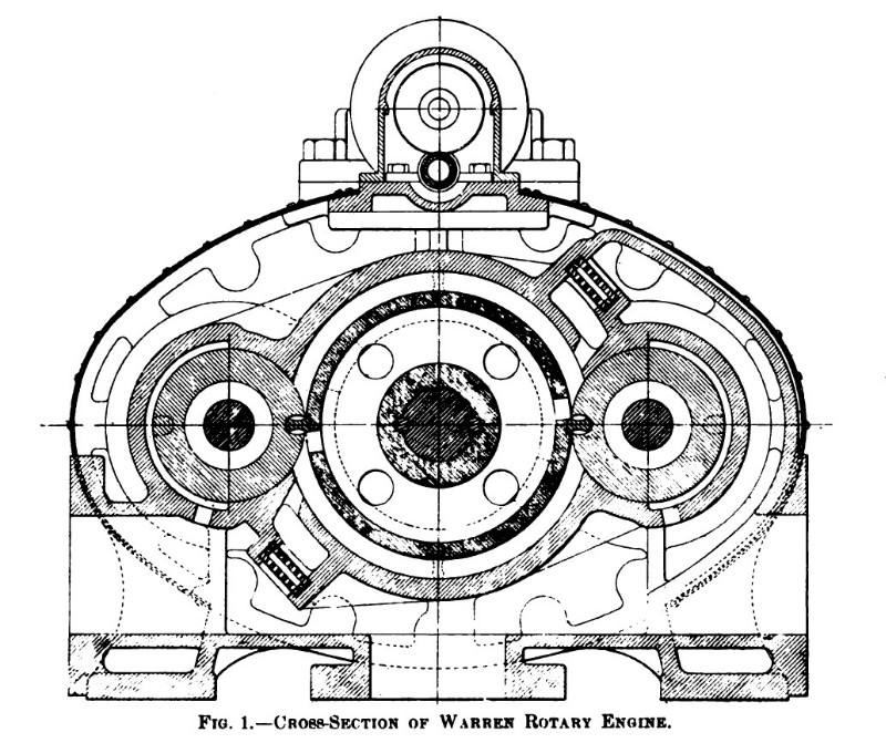
The method by which this is accomplished will be understood from an examination of the accompanying drawings. Fig. 1 represents a cross-section of the engine. It will be seen that this consists of a cylinder mounted between rotary abutments. The cylinder carries projecting vanes or pistons, which, during rotation, pass the rotary abutments by means of suitable openings in the latter.
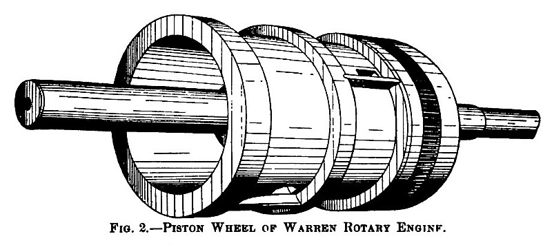
Fig. 2 represents the driving or piston wheel. It consists of a cylindrical casting mounted on a shaft, and provided with three flanges, between which are seen the pistons. After the pistons have been placed in position, the wheel is turned with a taper of one-sixteenth of an inch to the foot. The cylinder is bored out to the same taper, so that when the driving wheel is placed in position, and adjusted axially, the desired pressure-less contact can be obtained. The web of the driving wheel is perforated, and steam being admitted at the centre passes through ports to the ends of the wheel, thus equalizing the pressure. However, since the wheel is slightly larger at one end than at the other, there will be a small resulting end thrust, tending to force the wheel further into the cylinder. To prevent this and to hold the driving wheel in its proper position, an adjustable thrust bearing is mounted on one end of the driving shaft, which allows the wheel to be set in the first instance and locked in position. This construction, while securing the desired pressure-less contact, also enables it to be maintained in operation. The thrust bearing is so proportioned that as it wears down, it allows the driving wheel to move axially and maintain grazing contact between its flanges and pistons and the cylinder.
These points cover the essence of the whole design, though in its development a number of important minor considerations have been met. The rotating abutments gears, at double the speed of the driving wheel, but their diameter is so proportioned that there is a difference in velocity at the surface of contact of about 600 feet a minute. This gives a sliding contact, which will cause the two surfaces to wear in harmony. The abutment rolls between the flanges of the driving wheel, but it is so proportioned that the pitch circles of the abutment and flanges have the same velocity, and there is therefore no tendency to wear at this point. The abutment is adjustable axially and follows the driving wheel. It is held up to the latter, against the tendency of the steam in the cylinder to force it away, by means of small balance pistons which exert opposing pressure upon the abutment journals.
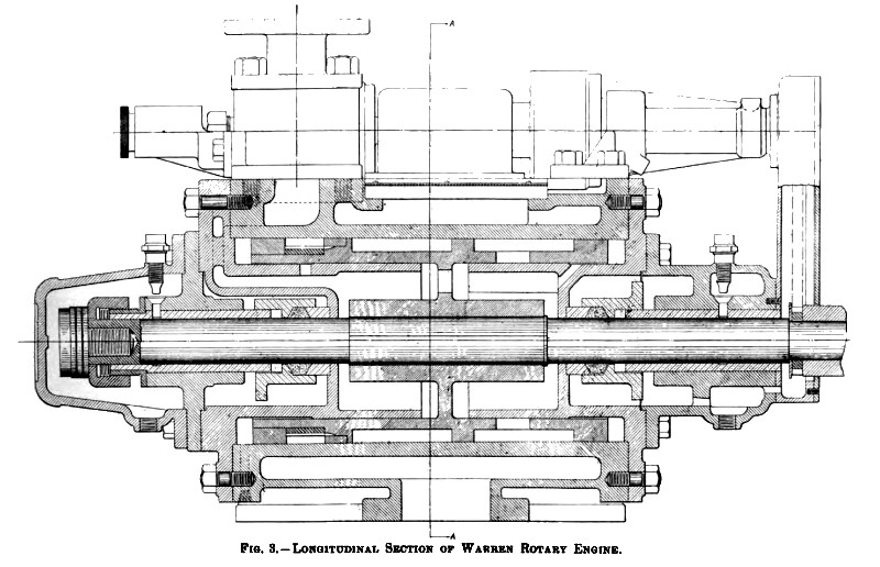
Fig. 3 shows a longitudinal section of the engine, giving an idea of how steam is admitted to the wheel and the pressure equalized. Passing down from the steam pipe and through the governor—shown in the outline at the top—it enters a central chamber, and through ports in two drum valves formed integral with and projecting inwardly from the end covers, is admitted through corresponding ports in the driving wheel to the working cylinder.
The drum valve and the inner surface of the working wheel operate with a running fit. No attempt is made to obtain a perfectly steam-tight joint here, as the slight leakage which takes place simply tends to raise the expansion line of the steam in the working chamber. As the journals wear, and the working cylinder tends to settle, the leakage at the bottom surface will be greater than at the top; but this will cause a greater average pressure of steam in the lower working cylinder than the upper, which, in turn, will tend to raise the cylinder off its bearings. This process may go on until the unbalanced pressure in the lower cylinders is sufficient to prevent further wear of the bearing. Steam-tight glands prevent escape of steam along the axle. The shaft is of ample size to secure rigidity and the main bearings are brought as close together as possible for the same purpose. The driving wheel is very carefully balanced to avoid vibration, as are also the rotary abutments, the latter having for this purpose, a hole drilled through diametrically opposite to the opening which receives the working abutment. As the mechanical construction of these parts is simple, balancing is easy to secure.
The driving wheel, shown in Fig. 2, is divided into two parts, in order to secure uniform rotation. Advantage has been taken of this construction to make a compound engine, steam being admitted first to one space and then passing to the other; but it is thought that a better design is secured by making each machine a single expansion duplex engine. If compounding is desired, two engines of the proper relative proportions are then coupled end to end, each machine being a standard duplex single-expansion engine. The process could be extended, if desired, making a triple or even a quadruple-expansion engine. This plan will also standardize the units, making it necessary to build only a few sizes. In any particular installation, the units selected will depend upon the steam pressure, the speed desired, and whether the engine is to be simple or compound. This system is exceedingly flexible, and by a suitable arrangement of piping and couplings it should be possible to drive a generator under any conditions of load, with the engine loaded to an economical point. Thus, assuming a compound engine, either unit could be operated alone or as a compound engine, or the two could be coupled together as two simple engines.
As explained, the engine has a fixed cutoff, and may be governed by a throttle governor or an intermittent governor, steam being admitted in blasts. A variable cutoff may, however, be used, by a construction which allows the drum valves to be shifted.
Fig. 4 represents this engine directly connected to a generator and gives a good idea of its appearance and the relative size of the two machines. Several of these engines have been operating experimentally for considerably over a year, and an examination of them has convinced the inventor that his ideas will be realized in practice. The engine is now being put upon the market by the Rotary Engine Company, 135 South Second street, Philadelphia, Pa. It is at present standardized in sizes from 12½ to 130 kilowatts, the speed varying from 1,500 to 650 revolutions per minute. Larger sizes are being developed, together with a reversible type of engine for marine propulsion, but no details of these designs are yet available.
US Patent: 716,799
http://www.datamp.org/patents/displayPatent.php?number=761799&typeCode=0 |
|
 1904 Article-Rotary Engine Co.-Cross-Section of Warren's Rotary Engine
 1904 Article-Rotary Engine Co.-Piston Wheel of Warren's Rotary Engine
 1904 Article-Rotary Engine Co.-Longitudinal Section of Warren's Rotary Engine
|
|