|
Title: |
1861 Article-Ames Iron Works, Paye's Forge Hammer |
|
Source: |
Scientific American, V5, 06 Jul 1861, pg.1 |
|
Insert Date: |
4/11/2019 9:41:40 PM |
Improved Forge Hammer
It is surprising that so much novelty as is embraced in this invention should be discovered in connection with a tilt hammer. The object of the invention is to make the force of the blow adjustable, so that one hammer instead of several may be employed for various kinds of work.
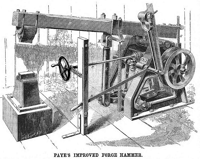
The arrangement is fully shown in the accompanying engraving. The helve, B, of the hammer, A, has its fulcrum near its end at c, and the spiral springs, dd, press the helve upward so as to balance the weight of the hammer, causing it to rest on or above the anvil with little or no pressure downward. The hammer is thrown upward for the blow by the connecting rod, E, which is operated by the curved arm, F, of the rockshaft, G; this shaft being rocked by the arm, H, upon its opposite side by means of the rod, I, which is connected at its upper end with a crank upon the shaft of pulley, J. The most important part of the invention is in the connecting rod, E. This rod consists of a hollow cylinder, with a piston inside, the piston o being connected with the helve by its head, K, and pressed inward by a stiff steel spring coiled spirally around it.
When the hammer is lifted up quickly by steam or other power, acting through the mechanism described, its momentum carries it still farther upward, drawing the piston partly out from the cylinder, E, and compressing the spiral spring, which always tends to keep the piston within r the cylinder. It is by the reaction of this spring drawing the helve and hammer down that the force of the blow is obtained. As the rock-shaft, G, is operated by a crank, the connecting rod, E, is being carried down during the descent of the hammer, thus keeping up the tension of the spring, and increasing the force of the blow. The lift of the hammer, and consequently the force of the blow, is varied at will by slipping the lower end of the connecting rod, E, along the curved arm, F, of the rock-shaft. This variation in the position of the connecting rod is effected by joining its lower end by means of the rod, L, with the arm, M, on the shaft, N.; this shaft having upon it a pinion, O, which meshes into a worm upon the shaft, P. Upon the opposite end of the shaft, P, is a hand-wheel placed in a convenient position for the operator, and it will be seen that by turning this wheel he can carry the lower end of the connecting rod, E, along the arm, F, thus varying the lift of the hammer. As the face of the blow depends upon the extent to which the piston of the connecting rod, E, is drawn from the cylinder, and as this depends upon the velocity with which the hammer is raised, the weight of the hammer being balanced by the spiral springs, d d; this force may be reduced far below that due to the falling of the hammer through any distance whatever, and may be regulated with great accuracy.
The engraving represents the hammer as operated by a belt provided with a friction pulley, Q, for starting and stopping it; this pulley being pressed against the belt or removed by means of the lever, R. The spring, s, at the end of the helve is employed, if necessary, in aid of the springs, d d, to counteract the weight of the hammer, and balance it on the fulcrum. The same lever, R, that operates the friction pulley, also actuates a friction brake which works against a fly wheel on the shaft of pulley, J, and which stops and holds the hammer suspended at any height desired above the anvil; superseding, by mechanism easily and safely operated, the dangerous and inconvenient gagging apparatus heretofore employed. The variation in the force of the blow may be made while the hammer is in operation. By this arrangement a much more powerful blow may be produced by a hammer of given size, and also a much lighter blow, than by the ordinary arrangement. It is also claimed to do a given amount of work with far less power than any other known. Three of these hammers are now in operation in this city; one at the Delamater Iron Works, one at the Allaire Works, and one at Fletcher & Harrisons, all giving perfect satisfaction.
The particular advantage claimed for this hammer is that it is adapted to all work, great and small, of a steam engine manufactory or other iron works.
The patent for this invention was granted October 9, 1860; and information in relation to it may be obtained by addressing the inventor, Edward Paye, or C. N. Delamater, who owns an interest in the invention, at the Delamater Iron Works, Foot of 13th Street, North River, New York.
US Patent: 30,343
http://datamp.org/patents/displayPatent.php?number=30343&typeCode=0 |
|
 1861 Ames Iron Works, Paye's Forge Hammer
|
|