|
Title: |
1855 Article-Low Moor Iron Works, Wilson's Patent Steam Hammer |
|
Source: |
The Practical Mechanic's Journal, V8, Nov 1855, pg. 175 |
|
Insert Date: |
3/17/2019 1:30:28 PM |
NASMYTH'S STEAM-HAMMER, WITH WILSON'S CYLINDRICAL VALVE. By MR. R. WILSON, LOW Moor Iron Works, Bradford.
The wonders of Mr. Nasmyth's invention, the "steam-hammer," have just received new lustre at the hands of Mr. Wilson, to whom belongs a large portion of the credit attaching to the early practical development of the beautiful automatic action of this invaluable tool. The special feature which Mr. Wilson has introduced, is his balanced pressure cylindrical valve, several modifications of which we noticed in our pages of' June and July last year. Hammers divested of all self-acting apparatus whatever and fitted merely with a hand-geared valve of this kind, exhibit an immensely improved action, enabling the workman to obtain the exact kind of blow he wants under all circumstances. This adjustment of the hammering force is attained just as effectually as with the simple hand-hammer of the smith; one stroke giving, perhaps, a mere touching tap, and the next, a blow of the highest intensity. Hence the newly arranged hammers are great favourites with the men who work them.
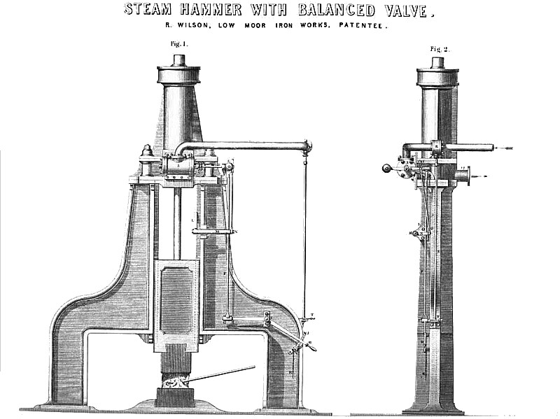
Our Plate 179 represents two views of a " Nasmyth" steam-hammer, as modified in its valvular arrangements to Mr. Wilson's views. Fig. 1 | is a front elevation of the hammer, showing its valve-chest, as replacing the original slide-valve. Fig. 2 is a corresponding side or edge view, taken at right angles to fig. 1. In these views, A is the cylindrical valve-chest attached to the old facing by a set of holts passing through new holt-holes bored in the facing, as the new chest is much smaller than the old one. The valve is worked by the short horizontal spindle, R, passing through a stuffing-box, c, in one of the end-covers of the chest. The outer end of this spindle is supported in a bracket hearing, d, bolted down to the platform of the hammer framing. Outside the bracket, on the end of the spindle, R, is a hack balanced lever, E, jointed by one end to the upper end of a long pendent rod, f, passing down by the side of the framing standard to the level of the governing workman's hand. The lower end of this rod, F, is jointed at o to the cranked hand lever, n, which turns on a fixed stud centre, is bolted to the framing. In working the hammer, this lever is simply moved up or down—an action which the character of the balanced steam-valve renders extremely easy. If the hammer is to be elevated, the handle of the lever is raised. If a blow is to be given, the lever handle is depressed; and in order that the intensity of the hammering blow may be regulated to the greatest possible nicety, the guard-plate, j, is fixed to the framing at a point close to the handle of the lever—the chained pin, K, Being contrived for insertion in the guard-plate holes at any desired height, for the purpose of defining the shift of the lever, as required for any special blow. The greater the range, or the more the handle is depressed after the elevating shift which has carried up the hammer, the more intense will be the descending blow. Hence the less the handle is depressed beneath the point at which the hammer is kept suspended by the steam pressure beneath its piston, the more gentle will he the hammer's downward traverse. But a little practice renders the guard-plate quite useless, as the men who are accustomed to work the valves very quickly find out for themselves how to give a blow of any necessary temper. It is this which brings even the largest hammers under the fullest control of the operator.
To prevent accident, however, under the management of an inexperienced man, a safety lever, L, is provided, the action of which is such, that if the hammer should at any time rise too high, the actuating steam is shut off, when the hammer gently descends like a piece of cork. This safety movement is equally as simple as the rest of the details. The lever, L, which is adjusted at an angle with the vertical line, is set upon the inner end of a short stud shaft, working in the long stationary hearing, M, Bolted to the main frame. The outer projecting end of this short shaft carries | a lever, N, jointed by its free end to the lower extremity of the rod, o, the upper end of which reaches to the level of the steam-valve spindle. This upper end of the rod is slotted longitudinally, to fit upon a stud pin fast in the side of the steam-valve lever, E. This slot allows of the ordinary working traverse of the lever, E, to its full extent, as actuated by the great hand lever below; the safety lever, l, not being the least affected thereby. When the hammer rises to its greatest elevation, the end of the inclined lever, L., coming in contact with the top of the hammer block, turns the short lever, n, upwards, and the consequent ascent of the rod, o, carries up the lever, E, turning round the steam-valve just so far as to cover up the ports, and cut off the ingress of the steam. This arrangement comes in well for full-length blows, as it communicates a slight depressing action to the hand-lever, H, when the attendant, taking the hint, depresses it still further, to give the proper blow.
Such of our readers as have examined the details of Mr. Wilson's balanced cylindrical valve, as previously illustrated in our pages, will he at no loss to see how it acts in the present instance in directing the steam flow. The working steam comes from the boiler through the horizontal pipe, P. The curved end of this pipe delivers the steam to the central portion of the valve casing, A, whence it finds its way by longitudinally divergent thoroughfares to the two ends of the internal oscillating valve-piece, and thence to the steam cylinder port. The exhaust steam passes off by the branch, Q, on the other side. The steam-pipe has a throttle-valve at r, from which a vertical rod, s, detaches to the standing place of the attendant, who can adjust the steam flow by the handle, T.
The balanced valve used at the Low Moor Iron Works, where the experiment was first tried, is eight inches in diameter, with ports fourteen inches long, by two inches wide. The steam pressure is 60 pounds, and yet a child of three years old could move the valve with ease, by working a sixteen-inch lever; so that with these improvements, coupled with certain others in the furnaces, the Low Moor forge-men can now do as much work with this hammer in nine or ten hours, as they formerly could, even with Mr. Wilson's last patented self-acting motion, in eleven or twelve hours.
Although this is a most beautifully suitable application of the valve, it has found many other important uses. The makers have now above a hundred of them at work for winding and common steam engines. With the winding engine-men they are especial favourites. In one case, where two 30-horse engines are fitted with them, the owner states that he saves £120 a year by each in oil and labour, whilst he gets more work out of his steam. A great fact in their favour is, that since their first fitting up they have not cost a shilling in repairs.
Great Britain patent #11,767 in the year 1847.
http://datamp.org/patents/displayPatent.php?number=184711767&typeCode=0 |
|
 1855 Low Moor Iron Works, Wilson's Patent Steam Hammer
|
|