|
Title: |
1903 Article-New Haven Mfg. Co., 34 in. Planer |
|
Source: |
Advanced Machinist, 1903, pg. 154 |
|
Insert Date: |
1/24/2019 1:14:06 PM |
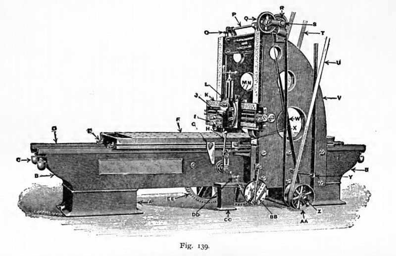
Fig. 139 shows a heavy planer designed to plane 10 feet long, 34 inches high and 34 inches wide. The cabinets A support the bed B, which has parallel, V-shaped grooves D, on its upper side. Drip cups, to receive the overflow oil from these grooves, are shown at C. The table F is moved by rack and gear; on its underside are parallel V shaped strips, which are fitted to slide smoothly in the similarly-shaped grooves D, on the bed; the wipers E contain felt to filter the oil entering the grooves, and also tend to keep them clean.
The long dog G strikes the rocker arm H, which has a removable arm for hand use; this rocker arm, through a system of mechanism, shifts the driving belts, reversing the motion of the table; X is the back or short dog; the cutter-head is on the cross-bar and consists of the tool-post I, where the cutting tool is clamped; J is the clapper or tool box, fastened to the vertical slide, or feed regulator, L, and swivels to any angle, being attached to the shoe N, which slides on the cross-bar K, thus giving the cross-feed or "advance" of the tool.
The down-feed or depth of cut is regulated by the handle shown over slide L. The head-lift bevel pinion O raises or lowers the cross-bar K, being geared to head-lift shaft P, on which is the spur wheel Q, geared into pinion S, operated by the pulley R and belt W, driven from the pulley shaft Z.
The front post, or housings, V, are of box-form in section, and are bolted to the sides of the bed, being connected at the top by a substantial box-shaped cross-girt. The pulley-shaft Z is driven by two driving belts; the forward, or cutting belt, T, and the backward, or return belt, U; the belts being moved on the fast and loose pulleys by belt shifter Y. The backing pulleys A A are shown in the illustration; the forward, or cutting motion pulleys, are on the other side of the bed.
The friction box B B revolves through an angle which is varied by turning the worm shaft D D, which moves a segment having stop-lugs, so placed that the lugs on the back of the friction box strike them, thereby actuating the cross-feed. E E is the center gear which meshes with the table-rack. |
|
 1903 New Haven Mfg. Co., 34 in. Planer
|
|