|
Title: |
1882 Article-Grant & Bogart, 14 in. Engine Lathe |
|
Source: |
American Machinst, V5, 04 Mar 1882, pg. 01 |
|
Insert Date: |
10/27/2018 8:20:42 PM |
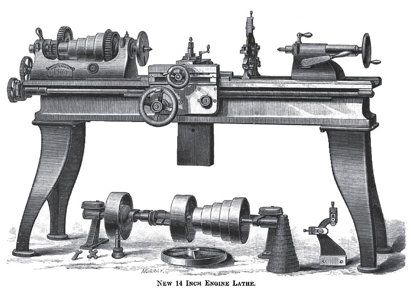
New 14" Swing Engine Lathe.
The engraving on this page represents a 14" swing engine lathe recently brought out as one of their standard line of machine tools, by Grant & Bogert, of Flushing, L. I. This lathe represents advanced ideas in machine tool design and construction, embodying the knowledge of many years' experience gained in the practical work of manufacturing this class of machinery. It is brought out and offered by the builders in the belief that those who buy and use machine tools will appreciate one of this class, in which no reasonable pains or material are spared where the addition of either would go to improve efficiency.
The bed is deep and of unusual strength and width, the latter insuring stability to the head and tail stocks, and the whole a firm and solid support for all the working parts.
The head stock is of extraordinary length, which affords room for a five-change cone pulley, with ample belt face, and also gives length to the spindle, insuring stability of motion and preventing chattering, particularly in doing heavy work in the chuck or on the face plate. The boxes are lined with the best Babbitt metal, tightly compressed in the shell before boring and fitting, it being the experience of the builders that, with journals of proper size and correctly fitted, this metal is superior to anything that can be used for the purpose. The boxes are enclosed in the jaws with caps rigidly bolted to the jaws, to prevent all tendency to play or to work loose, the adjustment being made, when necessary, by means of a line-threaded, centrally-placed screw, which abuts against a steel shoe, resting on the top of the upper half of the box.
The spindle is pierced with a central hole, 5/8 in diameter, for convenience in working up full-length stock, and for other purposes for which this construction is found desirable. The forward journal of this spindle is 2¼" in diameter by 3 5/8" in length, and is not shouldered over the box, but is the largest part of the spindle. This journal is hardened, after which it is "lapped" to as I nearly perfect condition of roundness and smoothness as is practicable, thereby insuring steadiness of running and freedom from jar. The thrust of the spindle is held at the back bearing against a broad, hardened steel collar, the adjustment being made by two screwed collars on the end of the spindle. This affords a ready and perfect means of adjustment, with no possibility of jamming the shoulder of spindle against the box flanges.
The back gears are of extra width of face and the most approved epicycloidal form of teeth, and to prevent the tendency to cumulative chattering, the pitch of the gears at the front end of the head stock is different from the pitch of those at the back end. By this means the tendency to isochronal jar, so often noticed when running on large work, is in a great degree obviated.
The yoke inside the head stock, which carries the idle pinions by which the direction of traverse of the carriage—as for cutting right or left hand screws —is changed instantly through the operation of a single lever and without the necessity for using an outside stud gear, is arranged with outside bearings for pinion studs, affording long surfaces for wear, and holding the pinions steadily to their work.
The tail stock has long bearing surface on the ways, and is strongly and substantially made. It is locked and unlocked from the ways by the use of a single lever, which operates an eccentric attachment underneath it. The spindle bearing is long. The tail spindle is 1 5/8 in diameter and is locked by a screw in connection with a split in the front end of the bearing. On the back side of the tail stock is arranged a neat cast iron shelf adapted to swing into convenient positions for holding a lamp, oil can or other accessories, while on the front side is arranged an oil cup and center oiler.
The slide of the taper attachment is fastened by means of a square headed screw, located so as to be come at readily. This screw, which for convenience in using is placed vertically in the back end of the carriage, is pointed or beveled at the end, and in being turned down to lock the taper slide the beveled point comes in contact with a correspondingly beveled shoe, which is by the operation forced against the slide, thus securely fastening it in any desired position. A slight turn of the screw—which is adapted to the use of the ordinary lathe wrench that is always at hand—releases the slide.
The slots in the carriage are milled to standard size, so that where several of these lathes are in use in one room, any attachments with which they may be fitted will be interchangeable between them. The gauge screws for the carriage slide, which in this class of tools usually cause trouble by becoming filled with dirt so that they must be removed and, as well as the nuts, cleaned as often as it is advisable to use them, are provided with sleeves that effectually exclude all foreign substances, leaving them ready for use at any time, without delay. Upon the outer end of carnage is arranged an adjustable water-can rest, by the use of which the drip can be brought to the work where it is the most desirable.
The lathe as here illustrated is fitted with a weighted rest, and is provided with an adjustable-jaw back and follow rest, two tool posts, two face plates, all gears necessary to cut screws from 3 to 48 threads, the necessary wrenches and a counter shaft, hangers and pulleys, the latter being fitted with an effective friction clutch which is noiseless in its operation. When desired, however, they are fitted with a gibbed rest, in which case an improved "doctor" rest is furnished. This is fitted and doweled in place, and made with two cast iron cans, the one for water and the other for oil, which forming part of the rest are always in place and ready for use.
Throughout, the workmanship of these lathes is excellent, the greatest pains being taken to scrape all wearing parts to perfect bearing, as well as to fit the head and tail stocks; by scraping, to the most accurate alignment of the spindles, and to bring the alignment of cross slide at right angles to the spindle alignment.
Every attachment is complete and ready for immediate use, and in all its parts and appliances the lathe presents a neat and creditable appearance. |
|
 1882 Grant & Bogart, 14 in. Engine Lathe
|
|