|
Title: |
1889 Article-Woodbury, Merrill, Patten and Woodbury Air Engine Co., 35 H.P. Hot Air Engine |
|
Source: |
Iron Age, V44, 26 Sept 1889, pg. 474 |
|
Insert Date: |
10/22/2018 9:42:06 PM |
A New Hot Air Engine
The air-engine of which we herewith present engravings has developed exceptional efficiency according to tests made by George H. Barrus of Boston. In concluding his report, Mr. Barrus states that “in view of the very large improvement that has already been made in the economy of the engine and in view of the evident losses, which have been referred to, which are still going on, it seems quite probable that an engine of this type can be made which will develop an indicated horsepower on a consumption of 1 pound of coal per hour, measuring the coal during a period beginning with the fires in a normal condition and ending with the fires in the same condition.”
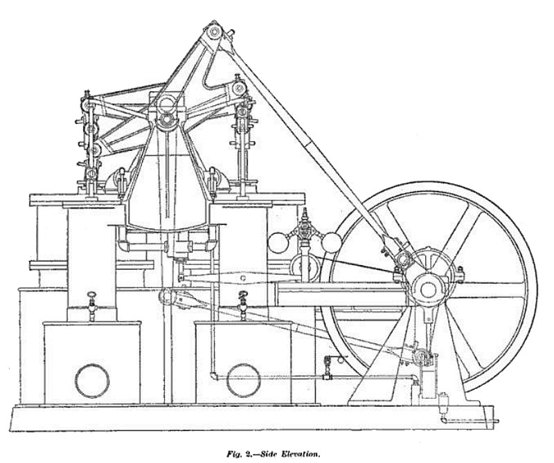
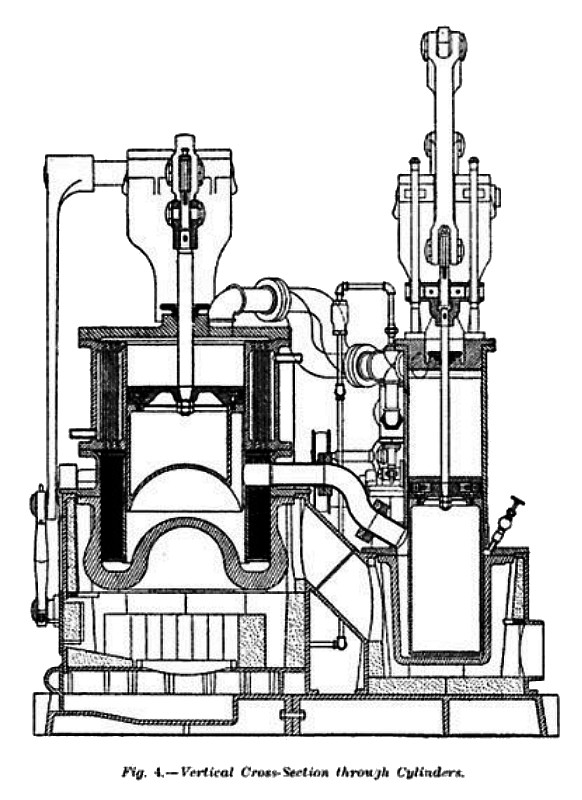
The general form of the engine and most of its details are represented by the accompanying engravings, Fig. 2 being a side elevation, Fig. 3 a top elevation and Fig. 4 a sectional and elevation through the centers of the working cylinders on one side. The engine consists of two working cylinders, which are double-acting, and two “reverser cylinders,” so called, all of which operate through beams and connecting rods upon the same fly-wheel shaft. The bottom ends of the No. 1 reverser and No. 1 cylinder are connected by a pipe; so, also, the bottom ends of the No. 2 reverser and No. 2 cylinder are likewise connected. The top of the No. 1 reverser is connected by a pipe with the to of the No. 2 cylinder and the top of the No. 2 reverser with the top of No. 1 cylinder. There is a furnace beneath each reverser and the flue from this furnace passes to a chamber surrounding the bottom of the working cylinder and thence to the chimney. Fig. 4 shows the arrangement of the principal parts. The furnace, heater and reversing cylinder are shown to the left, one above the other in the order named. The regenerator is below the cooler, both of which surround the reverser cylinder. The working cylinder is shown to the right. The only communication between the upper end of the reverser cylinder and the lower end of the same—that is, between the cold end and the hot end——is through the passages which form the regenerator and cooler. When the reverser piston moves downward, the air which is contained in this cylinder passes out of the space at the bottom, up through the regenerator and cooler, into the space left at the top; and when the reverser piston moves upward, the air in the upper part of the cylinder returns first through the cooler, then through the regenerator and finally into the space below the piston. The air in the reverser cylinder is, by this means, brought into alternate contact with the heater at the bottom and with the cold space at the top and is consequently alternately heated and cooled as the reverser piston works up and down. On its passage through the regenerator the air gives up its heat to the material of which the regenerator is composed, and when the air returns through the regenerator it picks up the heat previously given up. Being thus alternately heated and cooled, the air in the reverser cylinder, which has no outlet excepting through the pipe leading to the working cylinder, has its pressure alternately increased and decreased by an amount proportional to the range of temperature. Now, if we suppose that the reverser piston and the working cylinder piston are so connected by the mechanism that the working piston is made to move upward when the reverser piston is at the top of its stroke and downward when the reverser piston is at the bottom of its stroke, it will readily be seen that the Working piston will be subjected to the high pressure on the upward stroke and to the lower pressure on the downward stroke, and this difference of pressure will enable a working force to be generated. The reverser piston, having both sides in open communication with each other, is in substantial equilibrium, with the exception of the resistance due to the passages in the regenerator and cooler.
The reverser piston answers the purpose of a valve for the working cylinder, and its simple office is to transfer the air from the hot part of the chamber to the cold part and thereby to secure the desired increase and decrease of pressure. The object of the cooler, which is simply a tubular apparatus through which the water circulates, is to deprive the air of the heat which the regenerator fails to absorb and utilize. This sketch shows in a simple way the principles on which’ the engine works. The engine is made double-acting by employing two sets of these cylinders and by connecting them together by piping, as shown in the drawings, so that at the beginning of the stroke of either working piston, in either direction, one side of the piston will be in communication with the hot end of one reverser and the other side with the cold end of the opposite reverser.
The regenerator consists of an annular space 3¾ inches wide and 16 inches high, the outside diameter being 29 inches and the inside diameter 21½ inches, which is filled with wire-gauze. This gauze is made of wire No. 25 B. W. G., which is about 1/50, inch in diameter, 12 meshes to the inch each way, and it is placed in the regenerator in such a way as to completely fill the space. It is wrapped spirally around the center cylinder, and there are 102 courses. The amount of the superficial area of this gauze before it is introduced is approximately 1900 square feet. Each cooler consists of 640 tubes, made of copper, 18 inches long, 9/32 inch inside diameter, and No. 20 B. W. G., this last corresponding to a thickness of 0.035 inch. The air passes through the inside of the tubes, and the water which is used for cooling circulates around the outside. The tubes are held by means of heads 1} inches thick, and the amount of surface exposed to the air between the heads is 60.8 square feet on each side.
The engine is fitted with a governor, shown in drawing Fig. 2, which is of the ordinary centrifugal type. It acts upon a valve that opens communication between the top ends of the two working cylinders. The crank which drives the reverser pistons during the test above referred to was set about 70° ahead of the crank which is driven by the working pistons. The relative positions of the reverser pistons and working pistons at different points in the stroke was determined by turning the engine over by hand and drawing a short vertical line with the indicator-pencil at four points, namely: 1, When the No. 2 piston was at the beginning of the down stroke; 2, when it was at the end of the down-stroke; 3, when the No. 2 reverser was at the top, and, 4, when the No. 1 reverser was at the top. Measuring the distances of these marks from each other, it is found that the No. 1 reverser is at the top of the stroke when the No. 2 piston has moved over 56 per cent. of its down-stroke, and the No. 2 reverser is at the top of its stroke when the No. 2 piston has moved over 40 per cent. of its down-stroke.
The draft of the chimney for the engine is regulated by hand, a damper being place in the flue leading from each furnace. The engine is arranged so that it can be worked at any desired initial pressure of the air, a pressure-tank being provided, which is kept supplied with air by means of a small air-compressor, which is worked by an eccentric on the main shaft, shown in Figs. 1 and 2. The diameter of the cylinder of this compressor is 4 inches and its stroke 6 inches, and it is single-acting. The dimensions of the pressure-tank are—diameter 24 inches, length 5 feet. This engine is built for a working pressure in the tank of nominally four atmospheres—that is, 45 pounds by the gauge; but it has been worked for a short time at a pressure in the tank of five atmospheres. It is claimed that there is no limit to the pressure which can be carried in the machine, except that which relates to the strength of the parts. The pressure in the tank is that of the lowest pressure in the engine, corresponding to the back pressure in the ordinary steam engine, and the heating of the air serves to carry the highest extreme of pressure above this point. The pistons of the engine for all the cylinders are packed with simple cast-iron ring packing, each set out with springs. It will be noticed by referring to Fig. 4 that the pistons of both cylinders are very deep, the packing being located on the top, and this provision is made so as to keep the rubbing-surface of the packing as far as possible away from the hot end of the cylinder. The lubrication of the cylinder is effected by means of cylinder- oil in the manner of ordinary steam-engines, though the oil requires to be pumped into the cylinders rather than fed automatically.
The furnaces are lined with fire-brick, and beyond this there is no protection against radiation, all the cylinders and exterior of the furnaces being bare. The engine, which was tested—that is, the No. 13-—occupies a floor-space of 7.1 X 11.6 feet. The extreme height over all feet and the weight is 12 tons.
In our opening paragraph we quote Mr. Barrus’ opinion regarding the possibilities of the engine. We quote as follows from his report: “ The results of these tests show that the engine is capable of transmitting through the belt an effective horsepower for not more than one-half of the coal required for the best steam-engines of small power which are commonly used, the assumption being made that ordinary engines of this size use about 5 pounds of coal per indicated horse-power per hour and about 6 pounds per brake horse-power. These results do not appear to be the best that can be obtained from this type of engine, for there is a considerable loss of heat from the unprotected exterior surfaces of the furnaces, due to radiation, which might easily be prevented by the use of suitable covering. There is also loss from the exterior surfaces of other parts of the engine, from the same cause, which might also be prevented. It is believed, also, that the engine is capable of giving better results with some changes in the proportions. This opinion is offered for the reason that the present engine is so far in advance in the matter of economy of fuel over a previous engine, which the writer tested several years ago.”
This engine is built by the Woodbury, Merrill, Patten & Woodbury Air Engine Company, of Boston, Mass. |
|
 1889 Article-Woodbury, Merrill, Patten and Woodbury Air Engine Co.-35 H.P. Hot Air Engine (Side Elev
 1889 Article-Woodbury, Merrill, Patten and Woodbury Air Engine Co.-35 H.P. Hot Air Engine (Top Eleva
 1889 Woodbury, Merrill, Patten and Woodbury Air Engine Co.-35 H.P. Hot Air Engine (Vertical Cross Se
|
|