|
Title: |
1921 article - HSG Lathe |
|
Source: |
July 1921 Machinery |
|
Insert Date: |
10/18/2018 7:58:13 PM |
HOUSTON, STANWOOD & GAMBLE LATHE
A newly designed heavy-duty triple-geared lathe of 60-inch swing has just been built by the Houston, Stanwood & Gamble Co., Cincinnati, Ohio. This machine is shown in the accompanying illustrations. The bed is a one-piece casting, 42 feet long, and the total weight of the lathe is approximately 40 tons. The machine is driven by a 35-horse-power variable-speed motor mounted on the headstock. An additional motor is furnished on the left end of the apron, affording rapid power traverse to the carriage. Two steady-rests are provided, the larger having a capacity for work from 23 to 37 inches in diameter, and the smaller, from 2 to 23 inches in diameter. The jaws of these steady-rests have bronze shoes.
The various spindle speeds are obtained by operating the levers and handwheel on the headstock, and the different positions of these are designated by letters to enable an operator to determine a speed readily by referring to this speed plate on the headstock casting. The majority of the headstock gears have a pressure angle of 20 degrees. Lubricant is delivered to the headstock by means of a pump mounted at the rear of the lathe, which is driven from the motor shaft. To insure that the oiling system is functioning properly, an indicator is located on an oil-feed line from the pump to the headstock. This indicator has an aluminum wheel which spins rapidly when oil is flowing. The wheel may be observed through a glass at the front of its container. A device is provided to prevent oil from flowing up on the motor pinion and leaking out through the housing. Fig. 2 shows a rear of the gear-box located on the bed beneath the headstock, and gives an idea of its rigid construction.
Starting, stopping, and reversing of the motor on the headstock are controlled from a controller mounted on the right-hand end of the apron. The action is transmitted through the horizontal shaft near the bottom of the bed and through sprockets and a chain at the right-hand end of the bed, which connect with a second horizontal shaft at the rear. A long ratchet lever is provided at the left-hand end of the apron for exerting great pressure during a hand adjustment of the carriage, or for use in feeding the carriage along the bed under heavy cuts. A full-swing rest is mounted at the left-hand end of the carriage. Power traverse of the carriage is obtained by operating a lever on the apron, which engages a friction clutch. By moving this lever toward the operator, a positive clutch is engaged, which allows the carriage to be traversed by hand. The controller of the traversing motor is so constructed that the operator must hold the controller handle in position in order to run the motor. When the handle is released, it springs back to a neutral position. The friction clutch lever also springs to a neutral position when released.
A detailed view of the rear of the apron is shown in Fig. 3. There is an interlocking mechanism between the half-nuts for the feed-screw, the bevel gears, and large outer bearing of the rack pinion. The rack pinion has stub teeth with a 20-degree pressure angle. The front and back walls of the apron are dowelled and bolted together so that a practically solid box is obtained, which prevents the shifting of bearings out of alignment. The feed mechanism in the apron is driven through a positive angular-tooth clutch. This clutch permits feeds to be instantly engaged or disengaged without excessive strain on the operator's wrist. Both the front and back walls of the apron are bolted to the carriage.
At the right-hand end of the bed in Fig. 1, there will be noticed several supports for the lead-screw and control rod. One of the chief advantages of this type of support is that only a few seconds are required to remove a support and replace it at any position along the bed. Each support is furnished with bronze bearings for the lead-screw and control-rod, these bearings being accurately located on the hanger and fastened to it by means of a bolt. In a test on the lathe, a cut 1? inches deep was taken on a 16-inch diameter, 0.50 per cent carbon, hammered steel forging, at a feed of ¼ inch per revolution and a speed of 15 feet per minute. The cross-sectional dimensions of the tool used were 2 by 3 inches, and its length, 20 inches. |
|
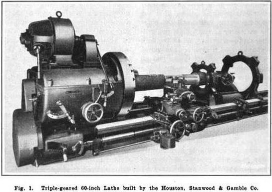 Figure 1
 Figure 2
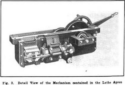 Figure 3
|
|