|
Title: |
1908 Article-Walker Grinder Co., #3 Surface Grinder |
|
Source: |
Southern Machinery, V7, May 1908, pg. 29 |
|
Insert Date: |
6/28/2017 7:38:41 PM |
THE NEW WALKER NO. 3 SURFACE GRINDER
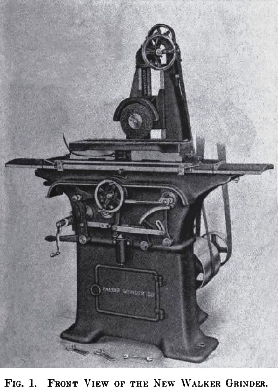
This new type of surface grinder, Fig. 1, is built by the Walker Grinder Co., Worcester, Mass. It is simple and rigid in design. The wearing surfaces are ample and the working parts are readily accessible. This machine is intended for continuous duty with the minimum of attention. Manufacturers will find this grinder useful for surfacing small parts which ordinarily are done on planer, shaper or milling machine. By the surface grinding method cost can be reduced and quality of workmanship improved. It is especially well adapted for finishing cast-iron parts that, are usually filed and polished, and, as coarse free-cutting grinding wheels of large diameter are employed, quite heavy cuts can be taken in stocking-out or roughing. The machine is equally well adapted for the ordinary grinding operations on hardened dies and general tool work. The base of the grinder is of T shaped cross section, providing a three-point bearing. The main bed, which is bolted to the base, has deep vertical cross section, and has apertures on the back side for the reception of projecting horns on the rear portion of the bed. The front and rear parts of the bed are bolted together, and the whole bolted firmly to the T shaped base. Extending into the interior of the main bed are widely separated V tracks, supported at the front ends by the horns. Upon these tracks is mounted a heavy wheel slide or housing, with corresponding legs or horns, on the front side, which extend through the apertures underneath the platen tracks nearly to the front wall of the main bed when the slide has been moved to its limit. This construction protects the cross-feed tracks, when the slide has been moved to its limit in a rearward direction. It also provides long bearing for the cross feed, and supports the housing slide to a point immediately under the grinding wheel. This construction is especially adapted to a surface grinder, as the weight supported is constant, and any length of main bed and platen can be used in connection with it.
The vertical slide of the grinding wheel is counterweighted to obtain an even movement and to prevent the disastrous result of slack forming in the nut or down feed screw. The grinding spindle carries wheels, which are mounted on interchangeable iron centers, fitting a tapered end of the spindle, which is hardened and ground and runs in hard bronze boxes, lubricated from oil rings from wells in the center of the box. The vertical feed hand wheel is graduated in thousandths of an inch and is provided with an adjustable index pointer.
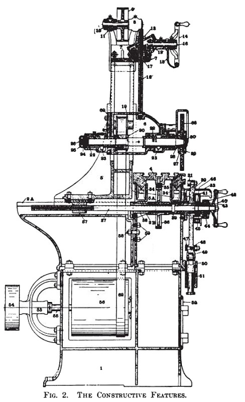
Two countershafts are included in the overhead drive, the first being belted to the second on three-step cone pulleys, so that proper speed may be obtained for the emery wheels as they wear down. Wheels for this grinder are selected for the duty they have to perform, and speeds should not be altered except for a considerable change in diameter of wheel. To provide for the necessary changes of wheel speed and to remove as far as possible the temptation to experiment, the changes are made at the ceiling. The platen is constructed on the well-tried lines of the iron planer, and has large V tracks oiled by rollers revolving in oil wells, held in contact with the tracks by spring tension. The length of the platen top equals the stroke of the machine, so that it may be ground off in place. It is regularly fitted with T slots for fastening down the work, and it is also adapted for receiving the standard Walker magnetic chucks. The builders are prepared to furnish this machine with a magnetic chuck built integral with the platen. When built in this manner the magnetic chuck takes up considerably less room in a vertical direction and jigs or vises can be held on the platen equally well by magnetism. Automatic cross feed is obtained at each end of the stroke of the platen. This is accomplished within a ¾ inch longitudinal movement of the platen, thus increasing the working period of the stroke. The cross feed can be automatically stopped at any point of its movement, with a positive stop at each end of its stroke, which also stops the platen. The platen can also be instantly reversed or stopped by hand at any time, and, by lifting one of the shipping dogs, the platen can be run to one side for the inspection of the work. Hand movement is obtained by means of a crank, which can be instantly disengaged when not in use. The accompanying illustration, Fig. 1, gives a front view of the surface grinder with a large magnetic chuck mounted on the platen. This chuck does not regularly accompany the machine, but the platen is provided with three longitudinal T slots for fastening down the work. It will be seen that the working parts are simple and readily accessible. A detailed cross section of the grinder is shown in Fig. 2, in which 1 is the base, 2 and 3 the rear and front parts of the bed, which are bolted together by bolt 5S, the whole being fastened to the base. 4 is the platen, provided with large V tracks, which are oiled by rollers 34, running in oil wells at the center of the bed, thus providing constant lubrication. 5 is the cross slide, or housing, for the grinding wheel, which is provided with forwardly projecting legs 5A, which extend through apertures to the front portion of the bed. The slide 5 works on V tracks, which are thoroughly protected when the slide is at its extreme rearward position. 6 is the vertical slide for the grinding wheel, operated by the screw 18 by means of the revolving nut 17 and the hand wheel 14. The spindle driving belt works around the drum 56, thence to the idler 9 on top of the machine from the outside, thence down and around the spindle pulley 20, thence upward over the idler pulley 19, and finally down again to the drum in the interior of the base. This drum is operated by a belt from the countershaft to pulley 54.
The spindle 21 is hardened and ground, and runs in hard bronze boxes 22, each being adjustable for wear. Lubrication is by the ring oiler 23. The emery wheels are fastened on iron centers, which are removably mounted on the tapered end of the spindle. The vertical slide 6 is also counterbalanced by a weight not shown.
This machine is substantially made with large wearing surfaces thoroughly protected from grit. The reversing is by means of a powerful friction clutch, not shown, but operated by the lever 47, which is in turn operated by the dogs on the platen in the usual manner. Three speeds are provided for the grinding spindle by means of step pulleys on the countershaft, and by means of a shift gear a fast and slow speed is obtained for the platen.
The capacity of the machine is 30 inches in length, 8 inches in width, and will grind 10 inches high with a full-sized wheel. The diameter of the wheel is 10 inches. The net weight of the complete machine is about 2,100 pounds. The machine can also be fitted with motor drive when desired. |
|
 1908 Walker Grinder Co., #3 Surface Grinder
 1908 Walker Grinder Co., #3 Surface Grinder (Sectional View)
|
|