|
Title: |
1872 Article-Lucius W. Pond, Engine Lathe & Metal Planer |
|
Source: |
Modern Machinery, V4, May 1872, pg. 105 |
|
Insert Date: |
2/28/2017 10:49:24 PM |
New Forms of Machinists’ Tools
Of the many machines forming the furniture of the work-shop, none are of greater value or more indispensable to the worker in metals than the engine lathe and planer. They have always been the favorite object of inventors, in adding continued improvements or modifications on their original form, and although these alterations thus calculated to promote their efficiency have been many and varied, each new step in advance has been gladly received and adopted by all in whose manufactures these machines fulfill their part.
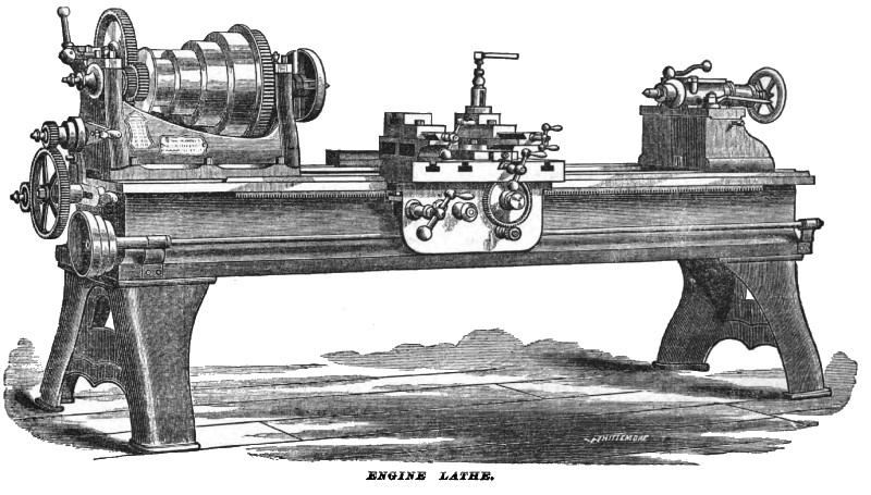
Our illustrations represent the newest and best forms of both lathe and planer, as manufactured by Mr. L. W. Pond, of Worcester, Mass. The new 20-inch lathe is constructed from new and improved patterns, and is fitted up in the most thorough and workmanlike manner. It has a very powerful geared head, low adjustable rest, heavy screw-gears and forged steel spindles. The head-block is webbed across beneath the cone pulleys on a new plan, which gives additional firmness. and admits of larger cone pulleys than is usual on this size, with gearing to correspond. The live spindle is of cast steel, and has unusually large and long journals, being 5 inches long by 2¾ diameter, running in hard bronze boxes. The cone pulleys are 12 inches in diameter largest, and 5¾ the smallest — four changes for 8-inch belt. The head block is secured by six large holding down screws passing through a flange outside. The tool-rest may be adjusted as to height without loosening the tool in the tool post, by means of an adjusting screw at the back which passes through a ball-nut in the upper part of the rest, and is fitted with a ball and socket at its lower end, to allow of motion for the upper part of the rest, which turns on heavy steel points and between heavy cheek-pieces cast on the lower portion of the front of the rest; the whole rest, thus firmly secured together, is locked or gibbed under the outer flange of the lathe bed, thus combining the two old fashions of locking and weighting. The whole rest, being broad and low, admits of the most swing (viz., 12½-inches) over it that is consistent with firmness, while the cross-screw will traverse the tool the whole distance from the centre to the circumference of the 30-inch circles without readjusting. The cross-screw is well protected from chips and dirt. The rest slides upon an inverted V, and bears only on the slopes, and will never wear loose. The rod or independent feed is independent of the leading screw which is used for screw-cutting only, and is therefore less exposed to in regular wear. This feed consists mainly of a quick and light running rod upon which is mounted a hardened and polished steel worm, which, through a large gun metal worm-gear and wrought-iron pinion, communicates with a wrought iron rack upon the front flange of the lathe-bed, and gives an even and powerful motion to the rod. This communication is made and broken, as occasion requires, to stop or start the rest, by means of a powerful and quick acting friction screw. The tail-block is secured by large holding down is bolts fitted with wrought-iron nuts tapped clean through and case-hardened. The counter-shaft is fitted with two wide, loose pulleys, and one tight and being larger than usual in diameter, requiring quicker motion of the driving belt, facilitates the reversing or starting and stopping, and effectually does away with the disagreeably noisy sliding clutch. and is less liable to get out of order than any known friction clutch. Iron cone pulleys and swivel-hangers, also hook and staple for the end of shipper handle, and an iron sliding rod with fulcrum screw and belt-guides all complete, are furnished with this shaft. An extra face-plate and centre rest, together with suitable wrenches, go with the lathe; all the small parts exposed to bruising wear are case-hardened; the whole making the most convenient and efficient tool now in use for general purposes.
The new 30-inch lathe by the same maker is also made from new and improved patterns in the most thorough and durable manner. It has a very powerful geared head compound rest, cross-feed, heavy screw gearing, and forged steel spindles with improved counter-shaft, centre rest, extra face-plate, and wrenches. The head-block is arranged as in the 20-inch lathe, and is secured to its bed by six large holding bolts. The live spindle has large and long journals, 6½ inches long by 4 inches in diameter. The cone pulleys are 20 inches in diameter the largest, and 9 inches the smallest; four changes for 4-inch belt. The compound tool rest is mounted on a broad, square base, and will traverse 10 inches in any horizontal direction, its lower circular flange being graduated to degrees of the circle, and the whole with the baseplate has sufficient traverse, horizontally and at exact right angle to the axis of the lathe, to face a disk 30-inch diameter without readjusting the cutting tool. A spiral step-ring is provided for the purpose of adjusting the height of the tool point. The right angle cross screw is furnished, near the front end, with a wrought-iron pinion which engages, at will, by means of a sliding intermediate gear, with the new patent power cross feed, which is acknowledged by all who have used it to be the simplest and moat efficient in use. It is driven from the main lead-screw by means of an ingenious and simple clamp connection, which effectually takes the place of slotting the lead-screw, and avoids the complication of the supplementary slotted rod, with the necessary gearing to drive it. The saddle, or main portion of the rest, slides on inverted V tracks, and bearing only on the slopes of the V, can never wear loose, and it also rests upon the tops of the inner tracks, thus reducing the span and greatly increasing the firmness of the rest for heavy boring and turning; and being locked or gibbed to the outer flange of the bed, it is better secured than by the internal spring and roller device used by some builders. A wrought iron rack and pinion, connected with suitable gearing and crank, serve to move the rest by hand. The tool-rest is locked to the saddle by a cut-under instead of a raised dove-tail, and the saddle having no upward projections, and being provided with convenient bolt slots, may be readily cleared of tool rest, etc., for convenience in boring steam cylinders, pedestal boxes, etc. There is also provided a tool-rest, fitted to either arm of the saddle, with a screw of 10 inches traverse for turning pulleys that may be equal in diameter to the full swing of the lathe. The saddle will allow of as much swing over it (viz., 21 inch,) as is consistent with the required firmness; and a mill or cylinder of 21-inches diameter, and as long as the full capacity of the lathe, may be turned in this lathe as readily and accurately as in a larger and more costly lathe of the old styles. The geared screw-feed is provided with a powerful train of cut gears, easily adjusted to three (or more to order) changes, varying from 85 to 18 to the inch, the connection with the rest being made by means of a long clasp nut, which is operated by a lever on the apron of the rest. The lead-screw is pitched 4 to the inch and is 2 inches in diameter, and cut by a Whitworth gauge. The tail-block is secured by large-holding down bolts fitted with wrought-iron nuts tapped clean through and casehardened. The countershaft is fitted with two wide, loose pulleys, and one tight, and being larger than usual in diameter, requiring quicker motion of the driving belt, facilitates the reversing or starting and stopping, and as in the 20-inch lathe, obviates the necessity of the sliding clutch. The same appendages already described as belonging to the smaller lathe are furnished with this one.
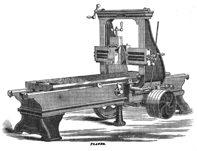
In size, etc., these machines vary from 13-inch swing (5 feet length of bed and 2½ feet turns, weighing 800 lbs.) to 10 feet swing; 30 feet length of bed and 15 feet turns, weighing 65,000 lbs. The new iron planers, made as represented in our second engraving, are nearly uniform in design for all sizes below 60 inches wide. They are from new and improved patterns, which, it is believed, combine simplicity with the greatest possible utility; correct workmanship, and the avoidance of costly superfluities, such as gaudy finish and useless patent gimcracks, being the great aim in their construction. The beds are very heavy, and strongly braced, and are mounted on short firm legs, fitted by planing off the entire bottom of the bed and the bearing spots on the legs, and secured by four large bolts for each pair, three or more pairs being supplied to beds above 10 feet in length. The tables are very thick and heavy; smaller sizes have holes drilled, while large ones have holes of a double rectangular shape, so made that no necessity ever occurs for the workmen to reach under the machine to pass bolts for securing his work. Three bolt slots, of uniform width and depth, are planed in every table, and “pockets" of considerable size are cast in each end of them to receive the chips and the tools of the workman. Tools are thus always within reach, and chips kept of? the track. Two heavy ribs are cast on the bottom of the table terminating in a V slide, so constructed as to give great additional strength to the table. In finishing these slides a serpentine oil-way is made, which, with oil pockets in the tracks of the bed, effectually prevents all cutting of the wearing surfaces, and insures smoothness and durability. The uprights or posts, having a breadth of base equal to the width of the machine, are firmly bolted to the cheek-pieces of the bed by large body-bound bolts, and additional security is afforded by a lip resting upon the upper edge of the cheek. These uprights carry the cross-bar upon their flat front faces, and hold it by means of a projecting lip, and a lock-plate of the simplest and most approved kind. The cross-bar has been greatly improved; by its peculiar construction the leverage on the fastenings is reduced to the least possible thing consistent with utility. It has heavy ribs cast on the back, and it is raised and lowered with the greatest facility by means of two elevating screws which pass up in a recess inside of the uprights, and connect with a cross shaft above the arch-piece by means of bevel gears, so that the bar is always kept horizontal by their simultaneous action. On all machines above 32 inches wide, the cross-bar is lowered and raised by power, effecting an immense saving of time and labor. The running gear of these machines is conceded to be the simplest and most durable in use; it consists of two simple trains of cut spur gears, through which power is communicated from the two driving belts (one cross and open) to the cut rack on the table. Parties using these machines are not subjected to the expense and annoyance that attend the use of small compound stud gearing, which wear out and clatter so frightfully after a short use, but they have a train of simple gearing that give effective and steady motion through the very large gear that engages with the rack while the machine is cutting, and a very rapid return motion without noise or clatter. Every enterprising master workman appreciates the value of a quickly returning planer above all things in his shop, and can easily see that this one can be made to return at any desired speed without changing the cutting speed by simply changing one pulley on the counter-shaft. The positive feed motion, recently much improved, is a very decided feature. By its quickness of action the greatest possible portion of the journey of the table is economized, and unlike all friction feeds which are a continual load, and most of all when they are doing no useful work, this feed does its work when little else is required to be done by the driving belt. Sometimes it happens that a belt that does the cutting with case, on a machine with a friction feed and compound gearing is quite unable to return the table at a decent speed. These annoyances are entirely avoided, and a greater amount of work is accomplished by using Pond's improved machine.
A simple arrangement of sliding gears on the cross-screw necessitates the use of but one pawl for the feed motion, and enables the workman to turn the feeding down-screw by means of the crank on the front end of the cross-screw, a matter of some importance on large planers, as there is no necessity of climbing upon the work when the upper crank is beyond his reach. These small gears as well as the bevel gears connecting the cross-rod with the upright screw, are of the best quality of wrought-iron. A simple device for disconnecting the cross-rod and upright screw is provided, and is a great convenience. The great power of the main gearing of these machines allows the use of very narrow driving-belts which run very fast, and reverse quickly. A counter-shaft with tight and loose pulleys, ahead and backing pulleys, hangers with swivel-boxes, iron shipper-rod and belt-fingers, hook and staple for handle, are included with these machines, and for large ones raising and lowering pulleys for the cross-bar. Suitable wrenches are also furnished. All small parts exposed to bruising wear are of wrought-iron and case-hardened. Double heads with independent feed motions for each tool are supplied for the large machines on special agreement. These planers vary in width from 22 inches and 4 feet length plane, weight 2,800 lbs., to 6 feet wide 36 feet plane, weighing 80,000 lbs.
Besides the machines already described, a new crank-planer possessing many points of advantage; a boring, turning, and slotting mill, made from recently-improved designs; pattern-makers' lathes, upright drills, index milling machine, and other valuable and improved forms of like tools, are made by the same manufacturer. Those of our readers desiring further information should address L. W. Pond, corner Union and Exchange Streets, Worcester, Mass, or No. 98 Liberty Street, New-York City |
|
 1872 Lucius W. Pond, Engine Lathe
 1872 Lucius W. Pond, Metal Planer
|
|