|
Title: |
1904 Article-Buffalo Forge Co., Vertical Steam Engine |
|
Source: |
Modern Machinery, V 16, #5, Nov 1904, pg. 502 |
|
Insert Date: |
2/10/2017 12:52:57 PM |
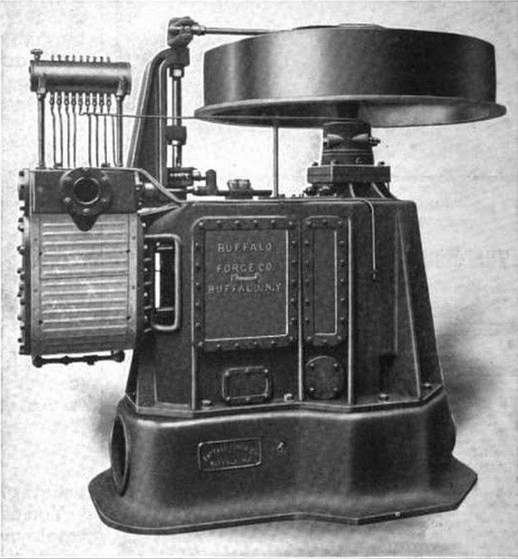
Occasionally manufacturers are called on to build special apparatus to meet unusual requirements, and such was the case when the Buffalo Forge Company received an order to build an engine with a vertical shaft. This order came from the Department of Docks and Ferries of New York City and was for an engine with a vertical shaft having two double-acting cylinders. The machine is truly unique, as it is the only one ever constructed of this type, and Webster gives the definition of unique as rare, uncommon, but one of its kind. The illustration shows the engine after coming from the testing floor of its builders.
The cylinders are made of the best close-grained charcoal Iron and are 10 inches In diameter with a 10-inch stroke. The piston is permanently fastened to the piston rod and when they are removed the lock nut at the cross-head is loosened and both can be taken out together. The steam is admitted to the cylinders by a single valve, of the piston type, and for this reason the cranks are set 180 degrees apart. Thus the steam distribution is secured by the use of a single valve controlled by one governor, located in the flywheel of the engine and supported on a steel plate attached to the arms of the wheel. The crosshead and crank pins together with the valve rod are of hardened tool steel. The ends of the connecting rods are forked and the wrist pins are fastened in them.
The weight of the main shaft, flywheel and governor and part of the connecting rod is carried by a thrust bearing situated at the top of the shaft, directly underneath the flywheel. The collar of the bearing is screwed on the shaft, and after it is in position, keyed, so as to prevent it from working off. This collar rests on three rings, placed one above the other, the central ring being made of hardened tool steel and the others of phosphor bronze. The weight is distributed over an area of 47.91 square Inches between the rings, and between the collar and the top ring this area is reduced to a value of 43.30 square inches. The total weight carried by this bearing is 1,750 pounds, so that the maximum pressure per square inch is slightly in excess of 40 pounds. The upper side of the collar fastened to the shaft has a recess turned in it and oil from a central reservoir is fed in here and finds its way, through oil grooves, down through the rings. The crosshead is of the locomotive type and its shoe completely surrounds the guide bar. The backing plate of the shoe is brass and the rest is cast iron lined with Babbitt. The connecting rods have marine boxes on the crank pin ends and are forked at the crosshead end, the pin having a tapered fit on each side. The ratio of the length of the connecting rod to the stroke is slightly over two. The main bearing bolts are made doubly secure with both a lock and a split pin. A flywheel with a flange turned on one side is provided for the engine and the crown of the wheel is but 5½ inches from the top of the wheel, so that the belt will tend to run above the flange, and not wear on the edge by contact with it. This wheel is five feet in diameter and has a breadth of 13 inches. One of the features of this engine is the oiling system, all the oil being taken from one central reservoir and supplied to the different bearing surfaces by tubes. Each tube has a sight feed arrangement connected to it before it enters the reservoir, so that at a glance the engineer can tell if any part of it is not receiving proper lubrication. This engine was installed on board a scow in New York harbor by the New York Dock and Ferry Commissioners and is used to operate a circular saw. This saw is mounted on a vertical shaft and utilized to cut off piling at a depth of 30 feet below the surface of the water. The saw is driven by a 10-inch belt and the peculiar construction of the engine prevented the necessity of a quarter turn in the belt. The engine is one of the enclosed type and so is well adapted for this rough work, as no dust, dirt or water will reach the working parts. Although many singular and difficult demands have been met by the designers of this engine, it maintains a high standard of economy in operation, regulates well and requires minimum attention while running. |
|
 1904 Buffalo Forge Co., Vertical Steam Engine
|
|