|
Title: |
1921 Article-Joshua Buckton & Co., 45 ft. by 6 ft. Locomotive Frame Plate Slotting Machine & 24 ft. by 8 ft. Planing Machine |
|
Source: |
The Engineer, 12 Aug 1921, pg.170 |
|
Insert Date: |
1/29/2017 9:52:41 PM |
Amongst the machines which were in course of construction and approaching completion at the time of our visit was a three-headed locomotive frame plate slotting machine capable of dealing with plates up to 45 ft. long by 6 ft. wide, and having a cutting stroke of 20 in. This machine is illustrated by Fig. 10 on page 170. It has a separate motor drive to each head, compound quick-return motion, and quick and slow power traversing gear for moving the slotting heads along the table and the saddles along the heads. It also has a gear for varying the length of the stroke without stopping the machine.
Fig. 2 on page 164 shows a 50 in. centre heavy sliding and surfacing lathe, admitting 16 ft. between centres. This lathe will swing 84 in. diameter over the saddles and has a face-plate about 10 ft. diameter provided with heavy screw jaws which are detachable when not required. The drive is through double, treble, and quadruple gear, the last pinion engaging in an internal ring of gear on the back of the face-plate. The changes of gear are effected by handles on the front of the headstock, the arrangement being such that no two gears can be put in opposition. The bed is of three-shear box section and carries two saddles with independent variable-feed motion for sliding and surfacing, the stopping, starting, and reversing of the feed being effected on the saddle itself. The loose head stock centre is set up by a geared screw. The machine is driven by a 35 horse-power direct-coupled variable-speed motor, giving with the gear changes in the head-stock, a wide range of cutting speeds for different classes and diameters of work.
Fig. 11 , page 170, represents a table planing machine to plane 8 ft. wide by 8 ft. high by 24 ft. long. This machine has two tool boxes on the cross slide, which are furnished with self-acting feed motions for horizontal, vertical, and angular cuts, and a tool box on each standard having self-acting vertical feed motions and horizontal and angular traverse by hand. The machine is driven by a reversing motor set arranged on the “Ward-Leonard" system, in which the actual driving motor is actuated by the current produced by a motor generator set, the reversal and speed variations being obtained through switchgear interposed in the circuit between the motor generator and the driving motor. The driving motor is direct coupled to the first spindle of the Buckton spiral driving system. This system, which is a development of the well-known "Seller's" type, consists of a spiral pinion having a pitch angle of 45 deg., driving a plain cut spur wheel, which is mounted on a diagonal shaft running through the bed of the machine at an angle of 45 deg. with the longitudinal axis of the bed. The diagonal shaft carries a second spiral pinion, which gears into a rack fixed beneath the table, at least four teeth of the pinion being simultaneously engaged in the rack. The amount of gear between the motor and the table is thus reduced to its lowest limit, consisting as it does of only two spiral pinions, one spur wheel, and one rack attached to the table. Thus the number and weight of revolving parts to be stopped and reversed at each end of the stroke is reduced to a minimum, which effects a reduction in the power absorbed by reversal. A further advantage claimed is that backlash is practically eliminated. At the same time the continuous smooth motion characteristic of spiral and screw gearing ensures the smoothest finish on the planed work. The feed gear to the tool-boxes is driven independently direct from the spindle of the motor generator and is automatically thrown in and out by a friction clutch, the feed being effected during the momentary pause at the end of the stroke. The reversing motor drive is normally set to give a high quick-return speed combined with a cutting speed which can be varied to suit the nature of the work in hand. For work which lends itself to double cutting the motor can be set to give a suitable cutting speed in both directions. |
|
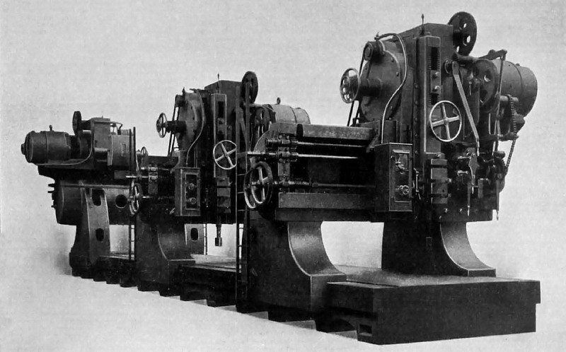 1921 Joshua Buckton & Co., 45 ft. by 6 ft. Locomotive Frame Plate Slotting Machine, Fig. 10
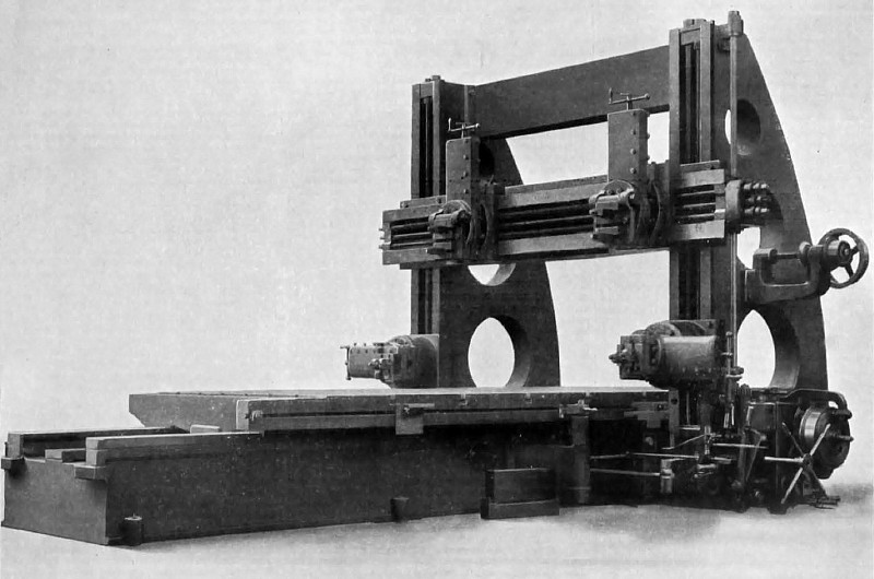 1921 Joshua Buckton & Co., 24 ft. by 8 ft. Planing Machine, Fig 11
|
|