|
Title: |
1921 Article-Joshua Buckton & Co.,40 ft. Plate Edge Planer, 50 in. Heavy Lathe, 400 ton Chain, Cable & Anchor Testing Machine |
|
Source: |
The Engineer, 12 Aug 1921, pg.164 |
|
Insert Date: |
1/29/2017 9:55:48 PM |
A rack-driven 40 ft. plate edge planer in course of erection is shown in Fig. 1, page 164. This machine, which is shown in the engraving in an unfinished state and without the holding-down beam, was designed to plane steel plates up to 40 ft. in length at one setting and, when required, a pile of plates up to 12 in. in thickness can be dealt with simultaneously. Plates of unlimited length can be fixed in the machine so that lengths beyond 40 ft. can be planed at two settings. The normal cutting speed is 40 ft. per minute. The saddle of the machine, which moves on broad sliding ways, carries, in addition to the tool slide and feed gear, its own motor and switchgear, which travel backwards and forwards with the saddle, collecting current from overhead wires fixed to the beam, on the same principle as the ordinary collector system of overhead electric tramways and railways. The motor is of the reversing type and the switchgear is automatically operated at each end of the stroke by adjustable stops on a rocking shaft running the full length of the machine. The saddle is driven to and fro by an arrangement of spiral gear similar to that used on Buckton's table planing machines, the motor driving direct on to the ?rst spiral pinion and the second spiral pinion, whose axis is at an angle of 45 deg. With the vertical, engaging in a rack fixed on the front of the bed. The ordinary method of driving plate edge planing machines by a long screw has obvious inconveniences beyond a certain limited length of machine. The rack system with the motor travelling on the saddle is, however, unlimited as to length and can be applied to any size of machine which may be required to suit present or future developments as regards the length of plates which it may be necessary to plane.
Fig. 2 on page 164 shows a 50 in. centre heavy sliding and surfacing lathe, admitting 16 ft. between centres. This lathe will swing 84 in. diameter over the saddles and has a face-plate about 10 ft. diameter provided with heavy screw jaws which are detachable when not required. The drive is through double, treble, and quadruple gear, the last pinion engaging in an internal ring of gear on the back of the face-plate. The changes of gear are effected by handles on the front of the headstock, the arrangement being such that no two gears can be put in opposition. The bed is of three-shear box section and carries two saddles with independent variable-feed motion for sliding and surfacing, the stopping, starting, and reversing of the feed being effected on the saddle itself. The loose head stock centre is set up by a geared screw. The machine is driven by a 35 horse-power direct-coupled variable-speed motor, giving with the gear changes in the head-stock, a wide range of cutting speeds for different classes and diameters of work.
Another machine which had just been completed was a 400-ton testing machine, which is shown in Fig. 3, page 164. It was designed, for carrying out breaking tests on three-link lengths of chain cable up to 4 in. diameter, and for proving anchors up to about 10 tons weight. It will admit a maximum stretched length of 16 ft. and will take in anchors up to 17 ft. in length. The pull on the specimens is applied by a hydraulic cylinder which is at the same end of the machine as the weighing apparatus. The ram of this cylinder pushes a sliding bed to which the outer end of the specimen is attached by shackles. The inner end of the specimen is similarly attached be a cross-head which, through a bell-crank lever, transmits the pull on the specimen to a weigh beam on the top of the column the machine. The weigh beam carries a travelling poise weight with scale and Vernier, which will read to the second decimal place of tons. To ensure accuracy in the readings thus obtained all the parts which transmit the load from the specimen to the weigh beam as well as the weigh beam itself have frictionless supports and frictionless fulcra, consisting of accurately ground hard steel knife edges on hard steel seatings. The knife edges and seatings are all readily renewable. Power for operating the machine is obtained from its own accumulator and motor-driven hydraulic pumps. |
|
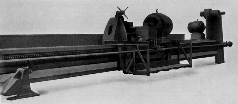 1921 Joshua Buckton & Co.,40 ft. Plate Edge Planer, Fig. 1
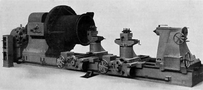 1921 Article-Joshua Buckton & Co., 50 in. Heavy Lathe, Fig. 2
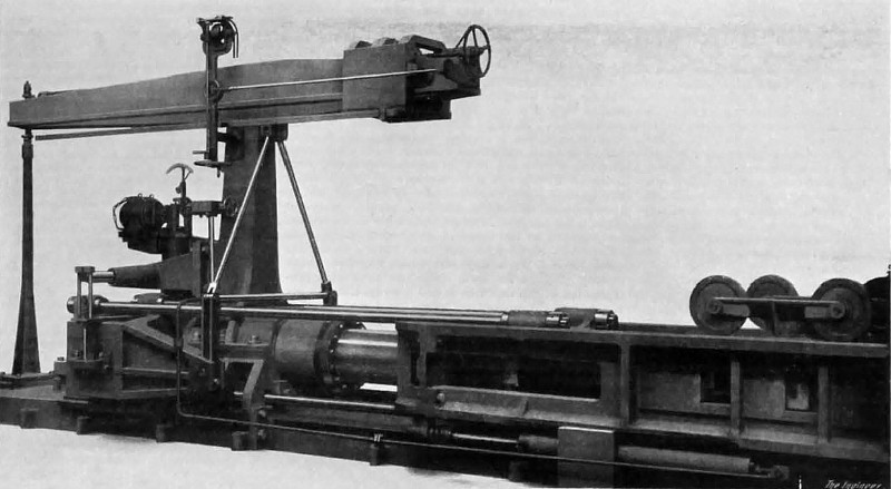 1921 Article-Joshua Buckton & Co., 400 ton Chain, Cable & Anchor Testing Machine, Fig. 3
|
|