|
Title: |
1860 illustration - Hall and Stewart's shingle machine |
|
Source: |
1860-01-07 Scientific American |
|
Insert Date: |
9/14/2016 1:20:52 PM |
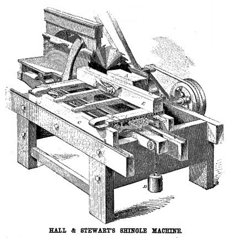
Improved Shingle Machine
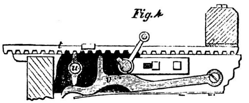
Notwithstanding all the ingenuity which has been expended on shingle-making machines, and notwithstanding the apparent perfection with which some of them work, our inventors still discover improvements which may be made in them, to secure either greater simplicity or more accurate operation. The annexed cuts represent a machine which possesses several novel arrangements, which is very simple, and produces admirable work. Fig. 1 is a perspective view of the machine, A being the block in the act of being sawed into shingles, B the saw and C the movable carriage to which the block, A, is clamped. The feed motion, by which the block is moved to the saw as the latter takes off the shingle, is effected by means of the pinion, j, Fig. 3, which meshes into the rack, k, which rack is pivoted at its left hand end to the carriage, C; the revolutions of the pinion sliding the carriage along the ways, l l, to the left. The two flat pins or studs, m and n, are driven firmly into the side of the rack, k, and project under the metal plate, o, which is firmly secured to the solid parts of the machine, and thus the rack is held down in gear with the pinion; but when the forward motion of the rack has carried the stud, m, from under the plate, 0, the weighted lever, p, by pressing upwards against the studs, m and n, lifts the rack, o, out of gear with the pinion, j, and thus the forward motion of the carriage is stopped. The stud, m, instead of being driven firmly into the side of the rack as stated, is, in fact, the bent end of a long red reaching from the end of the machine, which passes through a slot in the rack and may be slipped longitudinally to adjust the stopping point of the forward passage of the carriage to the length of the shingle block. The weight, D, is attached by a rope to the carriage, and is consequently drawn up as the carriage moves forward; but when the pinion, j, is released from its hold on the carriage by the of the rack, o, the weight, D, draws the carriage back to the right, bringing the left end of the block again to the edge of the saw. In this backward passage, the studs, m and n, slide along on the upper edge of the plate, o, thus holding the rack clear from the pinion, j, until the stud, n, slides from off the end of the plate, o, when the rack falls again into gear with the pinion, j, and the rotations of the latter being continuous, the forward motion of the carriage is resumed. When it is desired to stop the motions of the carriage to put on a block, without stopping the rotary motions of the saw or of the pinion, j, the catch, p, on the rod, r, is moved horizontally sidewise so that the latch, s, which is pivoted to the rack, k, may seize upon the catch, p, as the rack, k, rises, and thus the rack may be prevented from falling into gear with the pinion, j. The lateral motion of the block after each shingle is cut, by which the block is placed in position for cutting the succeeding shingle, is illustrated in Figs. 1 and 4. The timber, E, to which the moved block, A, is clamped, is fastened at its ends upon two racks, t and t‘, which slide in smooth grooves fastened to the solid parts of the machine. One of these racks is represented in Fig. 4, and its fellow is precisely similar. The cam, u, is secured rigidly to the end of a rod which is turned one-fourth of a revolution at the end of each backward passage of the carriage, by means of a spiral groove in a cylinder which is fastened upon it, coming in contact with a pin or spring which is rigidly secured to the solid parts of the machine. As the cam, u, is turned it presses down the spring catch, v, and slides along the rack, t, one cog, allowing the catch to return to its hold upon the rack. At the opposite end of the rod, a cam similar to u is fastened at right angles with u, so that, when the succeeding passage of the carriage turns the rod, u is merely brought in position ready to act while the cam at the opposite end of the rod moves its rack, the spring catch, v, holding meanwhile the rack, t, from moving. Thus, the two ends of the timber, E, are moved forward alternately, feeding the block laterally to the saw in a manner to cut the shingles of the proper wedge-shaped form. The mode in which the block is clamped to the side of the timber, E, forms a material portion of this invention, and is illustrated in Fig. 2. The claws or dogs, h h, are attached to the racks, i i, which gear into the pinion, f; the axle of this pinion passes through the timber, E, and has a handle upon its end, as shown in Fig. 1, by which the pinion may be turned, and thus the dogs are carried apart to receive the block and then brought with force against its ends, where they are held by the ratchet wheel, e, and spring catch, c. F is a revolving plane for jointing the edges of the shingles, The inventor says that one man only is required to operate this machine, and that with it he can saw and joint 1,000 shingles per hour, producing as handsomely sawed shingles us ever were made.
A patent for this invention was issued through the Scientific American Patent Agency, July 13, 1858, and persons desiring further information in relation to it will please address the inventors, Erastus Hall and Joel F. Stewart, at East Randolph, N. Y. |
|
 1860 Hall and Stewart's shingle machine, Fig. 1
 1860 Hall and Stewart's shingle machine, Figs. 2 & 3
 1860 Hall and Stewart's shingle machine, Fig. 4
|
|