|
Title: |
1921 Article-Pratt & Whitney Co., Die Sinking Machine |
|
Source: |
Machinery, V28, Oct 1921, pg. 162 |
|
Insert Date: |
6/24/2016 9:52:56 PM |
Several new points in design have been incorporated in the die-sinking machines made by the Pratt & Whitney Company of Hartford, Conn., to make their operation more convenient and their maintenance easier. The driving spindle has been provided with a positive pin lock in four positions, Bo that the chuck or collet can be tightened without holding the driving belt. The spindle pulley has a new system of oil-grooving opposite to the direction of rotation, so that oil is continually carried upward, thus insuring complete lubrication. A floating Babbitt washer takes the thrust on the spindle. The main driving cone has been fitted with a hollow spindle having communicating oil-holes that deliver oil to a series of felt-packed grooves which conserve the lubricant and guarantee an ample supply.
Leather wipers held in cast-iron caps attached to the knee protect the ways from chips and dirt. The vise capacity has been increased to accommodate larger work, and the vise has been strengthened in proportion to its greater capacity. A telescopic elevating screw is furnished in place of the old type of straight screw. The elevating wheel shaft is equipped with a thrust bearing for ease of operation. The outboard bearings for the knee and vise slides have been strengthened, and the slides are grooved and protected with covered oilers.
A cherrying attachment recently developed for use on the die-sinking machines is illustrated in Fig. 2. This attachment is pivoted in a bracket attached to the side of the column. When in the working position, the swinging arm of the attachment is doweled and clamped to a boss at the lower machine-spindle bearing. The application of the cherrying attachment does not interfere with the regular functions of the machine. When in the working position, the regular feeds are available for governing the cut, and in the non-working position the spindle is released for ordinary operations. The adjustment to either position can be readily made.
The backs of the cutter teeth are utilized for driving the cutters. These are made in the form of gear teeth and mesh with a spur pinion. Two pinions of different pitch are furnished to permit a variation in tooth space on small and large cutters. Bevel gears transmit power to the cutter pinion, and the end of the machine spindle is threaded to receive the driving gear. The mating driven gear is held on the pinion-shaft by a friction which may be readily-adjusted to suit conditions. This friction acts as a safety to prevent injury to cutters which might result from excessive feed or faulty manipulation.
Cutters from 1 to 6 inches in diameter can be accommodated, the cutter-slide being provided with an adjustment to compensate for the various sizes. The smaller size cutters are mounted on conical centers, while the larger sizes are provided with a comparatively small hole for which cylindrical centers are utilized. The method of mounting the cutters on centers is such that half the cutter diameter can be used. This cherrying attachment is intended for finishing operations only, and before its use the impression should be roughed approximately to shape. Stock cutters have a 7-degree angle plus a shrinkage allowance of 3/16 inch per foot. The cutters are made from carbon and high speed steels. |
|
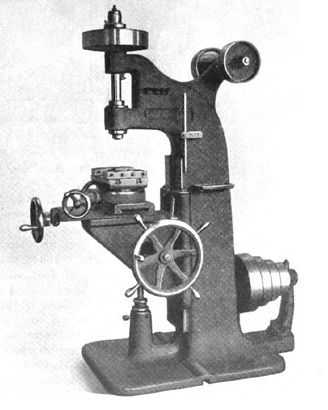 1921 Pratt & Whitney Co., Die Sinking Machine
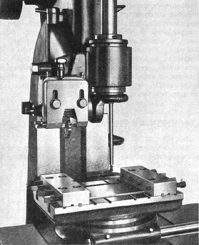 1921 Pratt & Whitney Co., Die Sinking Machine (Cherrying Attachment)
|
|