|
Title: |
1921 Article-Pratt & Whitney Co., Automatic Turret Lathe (Part 1) |
|
Source: |
Machinery, V28, Dec 1921, pgs. 282-284 |
|
Insert Date: |
6/24/2016 9:34:46 PM |
Various types of hand-operated and automatic turret lathes and screw machines have been developed for rapidly turning short work from the bar or while holding it at one end only; however, the engine lathe is still used in innumerable cases of quantity production, when the work must be supported on centers during turning. These cases include work which, because of its length or peculiar requirements as to accuracy or finish, can only be satisfactorily turned on centers; work which is turned in preparation for a later grinding or machining operation, the engine lathe permitting the turning to be done on the same centers that are afterward used for other operations; forgings and other irregular pieces which, on account of their shape, cannot be readily held in chucking machines; and work in comparatively small quantities which does not warrant the cost involved in setting up a turret lathe or automatic screw machine.
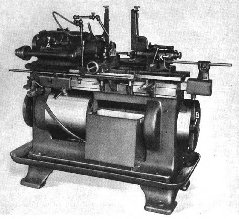
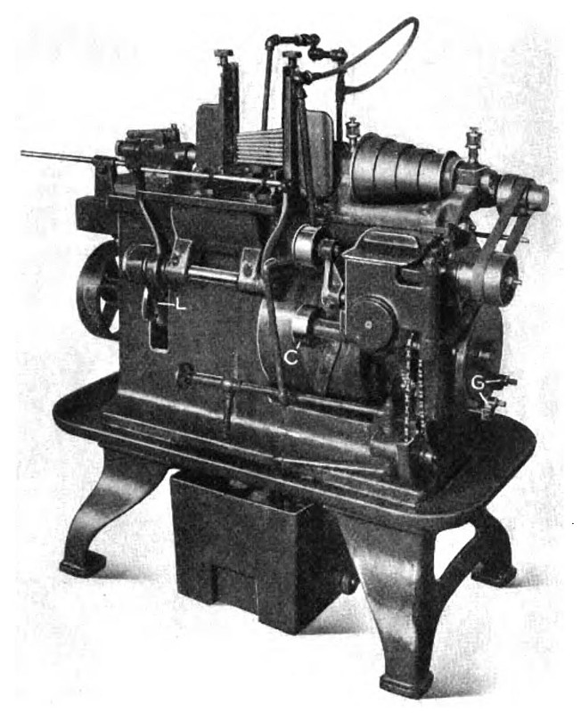
With a view to eliminating a large part of the cost of turning work such as has been described, and at the same time retaining the advantages of the hand-operated engine lathe, the Pratt & Whitney Co., Hartford, Conn., has produced the automatic lathe shown in Fig. 1 equipped with a geared head. The rear view of a smaller machine driven by a four-step cone pulley is illustrated in Fig. 2. These lathes have a headstock, tailstock, magazine for holding the work, and an automatic work-handling and control mechanism. The automatic mechanism places the work on the centers, adjusts and clamps the tailstock spindle, grips the work by means of the rotating chuck, which serves only as a driver, starts the feed of the tool carriage, releases the tailstock and chuck at the end of the cut, and, finally, returns the carriage to the starting position. These steps are repeated automatically for each piece of work so long as the magazine is supplied with blanks. After setting up, the only attention required is that of refilling the magazine, taking away the finished parts, and grinding and setting the lathe tools. Because of this fact it is possible for a battery of machines to be handled by one man.
Although these lathes are only now being introduced to the trade they have been used in the Pratt & Whitney shops for years in turning high-grade tap and reamer blanks and other similar work, and have proved their ability to rapidly and cheaply turn cut-off bar stock, forgings and other parts with the accuracy and finish generally obtained in good engine lathe practice. The smaller machine takes work from 1/4 to 5/8 inch in diameter and up to 12 inches in length, and has a carriage travel of 8 inches. The larger lathe takes work from 1/2 to 1 1/8 inches in diameter and up to 15 inches in length, and has a carriage travel of 12 inches. Many forgings of irregular shape and with a swing larger than the diameters given can be handled to advantage.
As previously mentioned, the lathe has been developed with either a cone-head or a geared-head drive. On the cone-head machine a belt from a countershaft drives the headstock spindle and feed mechanism, while a separate belt from the countershaft drives the automatic mechanisms at a constant speed. On the geared-head machine, one belt from a line-shaft drives the entire machine, all speeds and feeds being obtained within the machine. The number and range of spindle speeds is greater with the geared-head machine, and the drive is more powerful. Speed changes are made by shifting the ball-handle lever A, Fig. 1, on the headstock, in an H-slot to any one of four positions, and also shifting the adjacent back-gear lever. This gives a total of eight speeds. On the larger machine four feeds are available for each spindle speed, and on the smaller machine, three feeds may be obtained for each spindle speed.
The Camshaft Drive
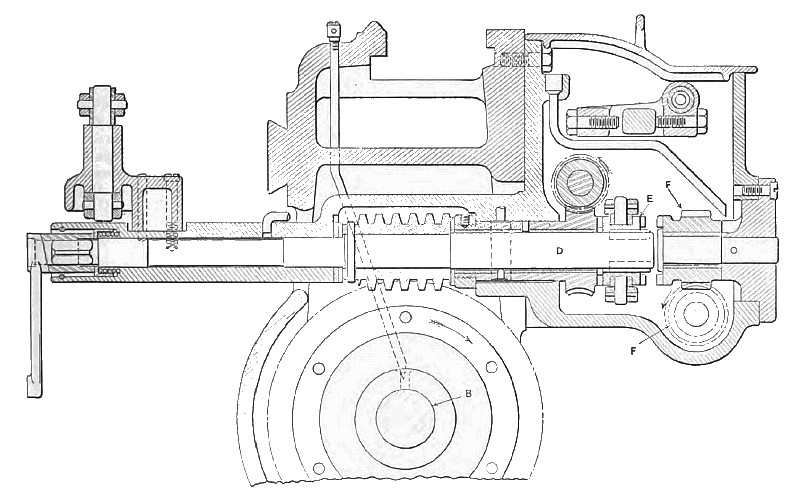
The cams which operate the automatic mechanisms of the machine are mounted on shaft B running the entire length of the machine. This shaft is rotated at two different speeds. The slow rotation is adjustable and gives the advancing feed for the carriage, while during the rapid rotation, which is constant, the chuck is opened, the footstock spindle withdrawn, the carriage returned, the stock from the magazine advanced, the footstock spindle advanced and clamped, and the chuck closed. Power for the slow rotation is obtained through the small cone pulleys seen on the end of the machine in Fig. 2. The center distance between these cones is adjustable so that the proper belt tension may be maintained. The lower cone shaft transmits power through worms and worm-wheels, clutch E, and shaft D to camshaft B, as shown in the sectional view in Fig. 3.
Power for the rapid rotation of the camshaft is delivered to the small plain pulley C, Fig. 2, on the gear-box, a swinging idler being provided to maintain a sufficient belt tension to operate the mechanism. Power is transmitted from pulley C through spiral gears F to clutch E, Fig. 3, the drive from this point to the camshaft being through shaft D and a worm and worm-wheel used In the slow rotation. The toothed clutch serves to throw in alternately the feed and high-speed mechanism, at predetermined intervals, being actuated through the medium of levers by adjustable trip-dogs G, Fig. 2, mounted on a disk at the left-hand end of the camshaft. The piping for the cutting coolant and the circulating pump, which is chain-driven at a constant speed, are also shown in the same illustration.
The hand-lever seen at the left-hand end of the machine in Fig. 4 gives a complete control of all machine movements except the rotation of the headstock spindle. Depressing this lever stops the rotation of the camshaft, and when it is raised and drawn forward, the camshaft rotates at high speed. When the lever is pressed toward the machine, the feed is thrown into engagement, and when elevated above the horizontal position, the feed will stop at the end of the cut to permit calipering or inspection of the work. The squared end of the shaft which is located below this control lever enables the machine to be operated by a hand-crank for trial when it is being set up.
The Carriage and Footstock
The carriage slides on the front of the bed and allows finished work to drop through an opening in the bed to the box below. The carriage has a cross-slide with adjustments on which may be mounted a tool-post and a follow-rest when needed. A jointed taper bar carried on a heavy bracket clamped to the front of the bed provides for turning taper work, and both straight and taper surfaces can be turned in one continuous cut. Various former bars may be substituted for the adjustable taper bar. The carriage is traversed the desired length of cut by the rotation of the large drum which carries cam straps, that, through a roller on slide H, Fig. 1, move the carriage-actuating rod J. Slide H is dovetailed to the bed. Provision is made for hand adjustment of the carriage by a rack and pinion which may be seen near the right-hand end of the machine in Fig. 1.
The spindle of the footstock is drawn back to release finished work and advanced to take new work by the operation of cams mounted on the pulley which may be seen at the extreme right-hand end of the camshaft. These cams, through a roller, move the slide mounted directly above it, and this slide, in turn, is coupled to a friction ring K on the footstock spindle. The rod connecting the slide and friction ring allows the footstock to be placed as far forward on the ways of the bed as the shortest work will require.
A slight slip of the friction ring takes place each time the spindle is drawn back, this being caused by the stop-collar on the front end of the spindle coming into contact with the front of the footstock casting. Therefore, when the spindle is advanced into contact with the work, the friction will again slip, insuring the proper contact with work inspite of variations in length due to inaccuracies in cutting off and variations in depth of centering. The pressure with which the center is brought in contact with the work maybe adjusted by the square-head screw on the friction ring. The footstock spindle is firmly clamped in place, after the center has made proper contact, by a further movement of the friction ring, which operates the horizontal lever over the footstock, thus forcing a plug on the spindle.
Construction of the Chuck
The chuck is mounted on the headstock spindle in such a manner that it floats laterally when necessary to compensate for inaccuracies in centering. Thus it can exert no lateral pressure on the work which is carried on the headstock center. Detail views of the chuck with the cover removed are shown in Fig. 6. At A the chuck is shown with the jaws drawn back ready to receive the work, which is inserted by the movement of the footstock spindle, as previously explained. The chuck jaws are moved into this position, while the lathe is running, by friction exerted on a drum carried by the chuck body. The friction is applied by the levers L, Fig. 4, and momentarily retards the rotation of the outer member of the chuck. This action not only draws the jaws back but also stretches the three springs shown in Fig. 6. Upon the release of the external friction, the springs move the outer member of the chuck in the forward direction, and thus swing the three jaws into contact with the work as shown at B.
An effective drive is obtained by the cam action of the jaws themselves without depending on the springs, and although the contact surface of the jaws is smooth so as not to mar the work, they will drive work under any cut which the lathe is capable of taking. The knurled surface on the outside of the chuck is used for setting it to the desired work diameter. Diameters between and including those indicated on the face of the chuck are taken care of by the rise of the cam surfaces on the jaws. Thus any size of stock within the capacity of the chuck may be driven if the knurled ring is revolved to the nearest indicated diameter on the chuck face. The alternate opening and closing of the chuck in proper sequence is controlled by a cam located on the camshaft directly beneath the headstock.
Operation of the Work Magazine
The position of the magazine, which is located on a bracket at the rear of the machine, is clearly shown in Fig. 4. The magazine consists of two uprights, adjustable to take both short and long work, and two guides on each upright adjustable to suit work of different diameters. Horizontal slides are provided for moving the pieces forward, one at a time, from the magazine to the machine centers. These slides are adjustable for all diameters within the capacity of the machine. As soon as a piece is brought into line with the centers, it is engaged at one end by the footstock center which pushes it endwise so that the other end enters the chuck and engages the headstock center. The tailstock is then clamped and the chuck closed on the work.
Yielding fingers are provided at the front of the transfer slides, so that when the work is securely mounted on the centers the slides withdraw before the lathe tool advances. In Fig. 4 the transfer slides are shown partially advanced with the work in place, the footstock and the carriage being removed so as not to obstruct the view. The transfer slides are operated simultaneously by levers shown at the rear of the machine in Fig. 2, which fulcrum on a horizontal shaft below the magazine. These levers, in turn, are actuated by the lever L which carries a roll engaging lugs on a cam. Leather friction washers are inserted between the cam lever and the adjacent vertical lever to allow slip in case work gets caught by being improperly inserted in the magazine.
Care was taken in designing the m a chine to make it fool-proof, yielding elements being inserted in the mechanism where trouble from irregularities in the work may occur. The geared-head machine can be driven by a constant-speed motor mounted on the rear of the bed. Fig. 5 shows a close-up view of an operation in which a heavy cut is being taken. |
|
 1921 Pratt & Whitney Co., Automatic Turret Lathe (Fig. 1)
 1921 Pratt & Whitney Co., Automatic Turret Lathe (Fig. 2)
 1921 Pratt & Whitney Co., Automatic Turret Lathe (Fig. 3)
|
|