|
Title: |
1921 Article-Colburn Machine Tool Co., #6 Heavy Duty Drill Press |
|
Source: |
Machinery, V28, Dec 1921, pg. 325 |
|
Insert Date: |
5/22/2016 10:36:34 AM |
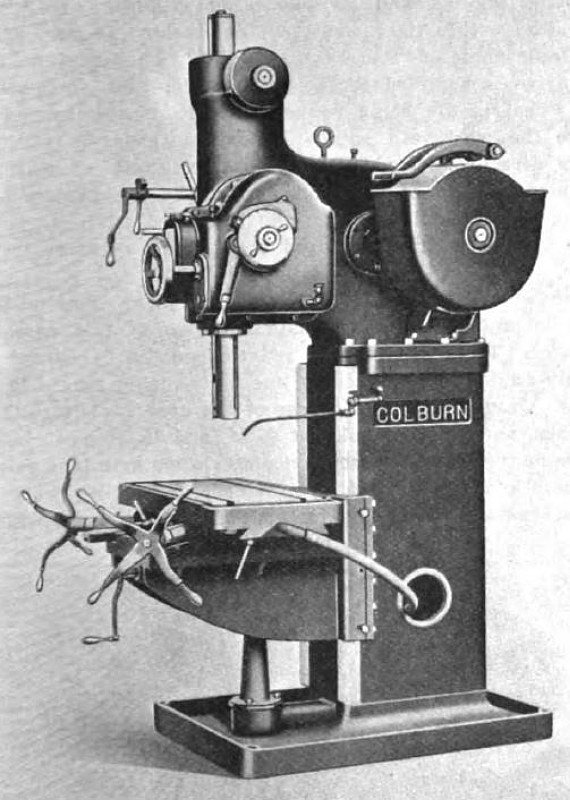
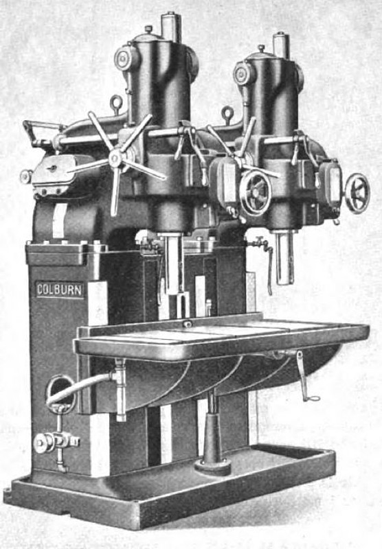
The Colburn Machine Tool Co., 1038 Ivanhoe Road, Cleveland, Ohio, has recently added to its standard line of drilling and boring machines, a No. 6 heavy-duty drilling machine, designed especially as a production tool, a variety of work being accommodated due to the wide range of speeds and feeds obtainable. The machine is built with either a plain or a compound table in a single-spindle style, or with a plain table in gangs of two, three, or four spindles. Fig. 1 illustrates the single-spindle machine equipped with the compound table, while Fig. 2 shows a two-spindle machine having a plain table.
The machine has a column and base cast integral, to the top of which is bolted the head casting. The lower section of the column contains a storage tank for cutting compound, openings on each side of the column affording access to this tank. A flexible pipe returns the compound from the table to the tank. The head casting serves as an oil-tight box for the gearing. The speed and feed gearing run in oil, and all other gearing is lubricated by a splash system. All vertical bearings are lubricated by means of wicks. To suit work of such a height that it cannot be placed between the table and the spindle, a special extended base having two T-slots and a finished surface may be furnished. In order to place work upon this base the regular table must, of course, be removed from the machine.
The spindle has a No. 5 Morse taper socket, is double splined to equalize the working strain, and slotted across the lower end to provide a means for driving large boring tools. A small slot in the side of the spindle is employed for keying drills or other tools to prevent them from turning during an operation. The spindle is driven at its largest diameter and near the lower end, by a heat-treated chrome-nickel steel bevel gear. The spindle sleeve is bronze-bushed, and has rack teeth cut directly on its surface. A self-aligning ball bearing takes the thrust between the spindle and the sleeve.
The speed change-box is located on the left-hand side of the head near the back. It has an oil-tight cover which may be readily removed to enable the gears to be changed to give the desired spindle speed. Two speeds are obtainable with each pair of change-gears by transposing them on the driving and driven shafts, while two more speeds are obtained by means of sliding gears operated by a lever at the front of the machine. A set of change-gears may be furnished, which, with the combinations of change and sliding gears, will give forty-eight spindle speeds ranging from 30 to 375 revolutions per minute. The regular equipment consists of one pair of speed change-gears, giving four spindle speeds as described.
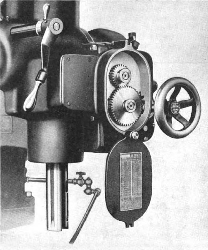
The feed-box is located at the front of the head near the feed hand-wheel, as shown in Fig. 3. The various feeds are obtained in a similar manner to the different speeds, that is, by changing two gears in the feed-box. Two rates of mechanical feed are obtainable with each pair of change-gears by simply moving the hand-wheel either in or out. By moving the hand-wheel midway between the extreme inward and outward positions, the power feed is disengaged and the spindle may then be hand-fed by revolving the hand-wheel or the capstan wheel on the side of the head, the latter method being employed to obtain rapid movement of the spindle. "With a complete set of change-gears, thirty-six feeds ranging from 0.005 to 0.134 inch per spindle revolution may be obtained. The feed mechanism is provided with a safety device, by means of which a pin is sheared, causing the feed to be stopped when the tool is operating under abnormal conditions, before any damage can result.
An interlocking device makes it impossible to change speeds while the machine is in operation, and this device also makes it impossible to start the machine until the sliding gears are fully in mesh. All control levers and handles are conveniently located at the front of the machine. An automatic tripping mechanism stops the feed when work has been drilled to the desired depth. The spindle is furnished with a spring counterbalance, the tension of which can be increased or decreased to suit the weight of different tools. The counterbalance also returns the spindle automatically after it has been tripped. A gear-driven tapping attachment having a ratio of 1½ to 1 is furnished when desired. This attachment is mounted on the driving shaft and driven by a pulley.
An oil-pan extends around the working surface of both the plain and compound tables. The elevating screw of the plain table is operated by a crank-handle, and is set off center to permit the boring of a hole through the table to accommodate boring-bar pilots. The compound table is mounted
on a special knee and has rapid longitudinal and transverse movements, which are obtained through gearing actuated by the capstan handles. These are so arranged that the operator can readily manipulate the table in both directions while standing directly in front of the machine.
This machine may be equipped with a motor drive, provision being made for mounting the motor directly on the lower portion of the column at the rear. A motor of from 10 to 20 horsepower is recommended, the size depending on the work being done. The machine has a working capacity for driving 3-inch high-speed drills through steel. Some of its main dimensions are as follows: Distance from center of spindle to face of column, 14 inches; vertical adjustment of plain table, 13 inches; maximum distance between nose of spindle and plain table surface. 36 inches; compound table, 30 inches; and working surface of plain table, 20 by 24 inches, and of compound table, 18 by 30 Inches.
On a machine of the gang type, each head forms a complete unit, this design permitting a number of heads to be mounted on a common column. All heads are interchangeable, a templet being used in drilling the bolt holes by means of which the heads are secured In place. Each individual unit is driven by a constant-speed belt from a line-shaft and connected with tight and loose pulleys on the head. Thus, any spindle may be stopped or>started independently of the others. The machine may also be driven from a countershaft attached to the rear. The table on three- and four-spindle machines is elevated by means of two screws, one at each end. A large capacity pump supplies coolant to all spindles. This pump is attached to the side of the column, and is driven from either the line-shaft or the countershaft.
The gang machine may also be equipped with a motor drive and tapping attachments. A ball-bearing countershaft is furnished with a motor-driven machine. The distance from center to center of the spindles on gang machines is 35 inches. The table is 20 inches wide and, on a two-spindle machine, 59 inches long. |
|
 1921 Colburn Machine Tool Co., #6 Heavy Duty Drill Press
 1921 Colburn Machine Tool Co.-#6 Heavy Duty Dual Spindle Drill Press
 1921 Colburn Machine Tool Co.-#6 Heavy Duty Drill Press (Feed Gear Box)
|
|