|
Title: |
1897 Article-Laurie Engine Co., Heavy Fly-Wheel Construction (Part 1) |
|
Source: |
American Machinist, V20, 03 Jun 1897, pg. 23-413 |
|
Insert Date: |
2/16/2016 9:44:42 PM |
A Canadian Example of Heavy Fly-Wheel Construction.
We show herewith some interesting views from the interior of the shops of the Laurie Engine Company, of Montreal, which illustrate some processes used there in connection with the construction of heavy fly-wheels which possess points of interest and novelty.
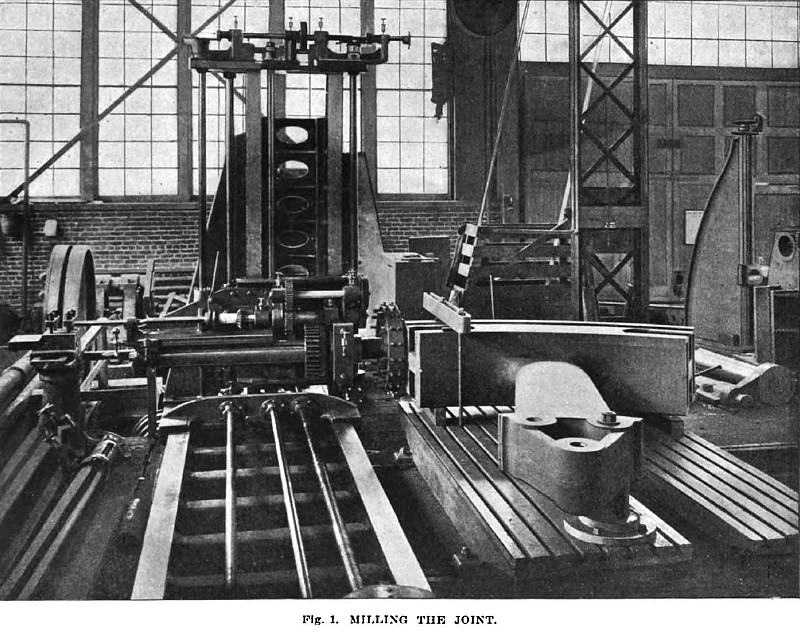
Fig. 1 shows a horizontal boring, drilling and milling machine, the operation in progress being that of milling off the joints of a heavy segmental fly-wheel, the method of doing the work being obvious from the illustration.
In laying out the segments, the Laurie Engine Company use a table of natural sines by which the chord for a given angle of segment can be determined with any required degree of accuracy, while errors of construction are reduced to a minimum. A planed board is attached to the casting, extending to the center of the shaft; an arc is drawn on the wheel rim and the chord laid down with prick punch marks. In setting the first arm on the milling machine, the board is left in place., the center point and extremity of the chord are set parallel with the frame of the machine, and the pivot pin seen, in Fig. I is located. When finished, a gage is made from the face of joint to the guide edge on milling machine, and the following arms are then set to this gage at the rim, the location of the hub ends being determined by the pivot pin.
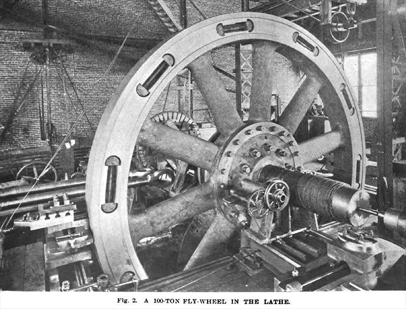
Fig. 2 shows the same wheel in the lathe with the operation of turning just completed. It will be seen that the wheel is turned upon its own shaft and practically its own bearings, although a portion of the shaft nearer the wheel than the actual journal is employed to carry the weight. The shaft is carried in temporary bearings which are made of frame castings Babbitted up in each case to suit the shaft being turned—the Babbitt being removed, re-melted and poured again should the next shaft be of different size, as, of course, it usually is. The lathe will be seen to be a pit lathe having some features which are not always found in such tools, the head as well as the tail stock being arranged to slide endwise upon the bed so as to admit the shaft, while the tail end of the bed slides on the foundation to open or close the pit.
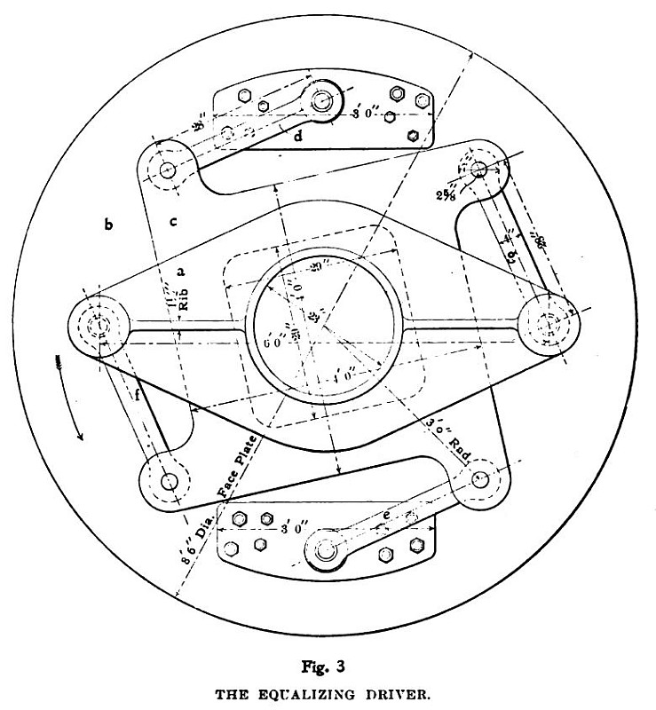
Were positive alignment of the shaft with the lathe necessary, a good deal of time would, of course, be consumed in securing such alignment, but, in point of fact, the necessity for this alignment is obviated by the use of an equalizing driver between the face plate of the lathe and the end of the shaft. This equalizing driver will be seen upon the face plate and through the arms of the wheel in Fig. 2, but its construction will be more apparent from the outline drawing, Fig. 3, in which a is a two-armed spider secured to and driving the shaft; b is the face plate of the lathe, and c is an intermediate floating or equalizing piece driven by the face plate and in turn driving the spider. Two links, d e, connect the face plate with the floating piece while two others, f g, connect the latter with the spider. It will be seen that this construction provides for any slight lack of alignment, and drives the shaft with a uniform turning effort and without side pressure in the bearings. To prevent end motion of the shaft, false or wobble centers are introduced between the lathe centers and the center holes in the ends of the shaft, one of which will be seen at the end of the shaft nearest the observer.
In operation the wheel is assembled piece by piece in the lathe. The shaft with the wheel center is first put in the lathe and the first segment put in place. The reaming attachment, which will be seen attached to the bearing which carries the shaft, is then brought into play, the bolt holes are reamed and the bolts put in place, this reaming attachment being driven by a rope drive from a small engine not seen in the illustration. After the first segment is in place the others are added one at a time until the wheel is complete. The T-links shown in place are temporary ones used during the construction of the wheel only. They are, in fact, bolts having right and left threads, and are screwed into place warm, so as to get an effective grip on the work. After the wheel is finished it is taken down one segment at a time, no floor work being done on it. One of the advantages of this method is, of course, that the crane handling the work can be much smaller than would otherwise be necessary. The wheel shown in the picture is 24 feet in diameter and 100 long tons in weight, the section of the rim being approximately 24 inches square. The capacity of the lathe is such as to take in wheels up to 30 feet diameter by 7 feet face.
Fig. 4 shows the same lathe arranged for doing small work, the bed having been slid on the foundation to close the gap. Another arrangement, not shown in the picture, enables the hub to be bored or facing to be done.
It is needless to say that wheels so made run true. |
|
 1897 Laurie Engine Co.-Fig. 1,Milling the Joint
 1897 Laurie Engine Co.-Fig. 2, 100 Ton Flywheel in the Lathe
 1897 Laurie Engine Co.-Fig. 3, The Equalizing Driver
|
|