|
Title: |
1903 Article-H. W. Ward & Co., Universal Cylindrical Grinder |
|
Source: |
Emery Grinding Machinery, 1903, pgs. 128-134 |
|
Insert Date: |
12/3/2015 7:46:32 PM |
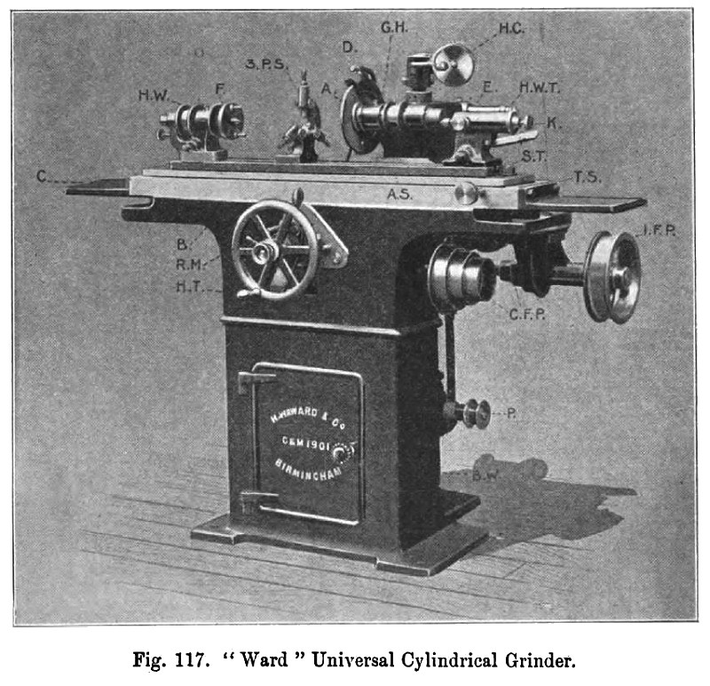
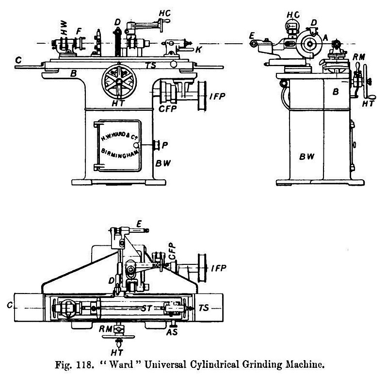
The "Ward" universal cylindrical grinder, fig. 117, is a general purpose machine. It meets all the requirements of tool-room or cylindrical work within its capacity, such as shafts, spindles, bearings, taper or parallel, external and internal work, gauges, collars, bushes, etc. The photograph fig. 117 gives a clear front view of the machine, and shows the various parts of the machine when ready for receiving a piece of work for external grinding. The photograph is lettered in conformity with the plan, front and end elevations, fig. 118, so as to enable the different parts of the machine to be traced. The machine is driven by three countershafts: the first receives its motion from the main shaft, and transmits motion by cone pulleys to the second and third countershafts, thus allowing a variation of speed both of the work being ground and of the emery wheel.
The headstock H W has a spindle running in adjustable bronze bearings, and can be swiveled for the purpose of grinding short sharp taper work in the chuck. A 4 inch universal chuck is used for work that has to be ground internally. For such work the spindle and chuck are driven by the pulley H W, which is seen in the centre between the spindle bearings. For external grinding the loose pulley F which runs on the front end of the spindle is used; this pulley is bushed with a bronze bush, so that whilst the rotating pulley moves the work, the spindle and centre remain stationary, and as the work therefore runs on dead centres it will be perfectly true. The tailstock H W T is arranged with a spring adjustment so as to allow of the removal of work for examination readily, and to provide room for any expansion due to heating that may occur, thereby ensuring a uniform pressure between the centres and the work. For instance, when the work has to be removed, examined and afterwards replaced for further grinding, it is released by pressing down the lever K giving motion to the barrel of the tailstock; then, having replaced the work, K is gently let back and the spring adjustment behind the tailstock centre comes into action, forcing the centre into its proper position by a pressure which is just sufficient to hold the centre up to the work.
The swivel table S T, with the work headstocks fixed to it, can be swiveled on a centre pin for 10 degrees in either direction, and by means of a graduated screw arrangement A S, reading to half degrees or inches per foot at the end of the slide, taper adjustments can be made with ease and accuracy.
The table slide T S, upon which the swivel table S T is mounted, runs in a vee groove on one side, and on a broad flat surface on the other. It travels automatically in either direction by means of a self-acting reversing motion, and the travel can be regulated to any distance within the limits of the machine; that is to say, for any length up to the full stroke of the table, which is 2 feet. There is also provided a fine adjustment by means of worms and wheels operated by small milled knobs, which can just be seen through the hand wheel on the front of the machine in the photograph fig. 117, but which are clearly seen in the front and end elevations, fig. 118. When it is required to make any considerable alteration in the length of travel, the worms may be thrown out of gear with the wheels, and the worm-wheels may be rotated by hand; in this way a rapid adjustment can be obtained; after having set the travel quickly to something near what is required, the worms and wheels may now be thrown into gear again, so that any final accurate adjustments can be made by means of the milled knobs provided for the purpose. The reversing fork R M, by which the reversing action is transmitted to the motion itself for automatically reversing the table, will be seen in the plan and end elevation fig. 118; it is situated behind the hand wheel H T.
The emery wheel spindle is carried in the headstock G H, fig. 117, and is fitted to rotate in adjustable bronze bearings; this headstock is fixed to a swiveling slide to enable the headstock to be so set that the whole cutting face of the emery wheel can be brought into contact when taper work is being ground. The emery wheel A is provided with a water chute D, and as the headstock G H is placed behind the work and facing the operator, he is conveniently situated for seeing his work clearly, and for using his right hand in testing the work; this is exactly the opposite to what happens in the example of internal grinding on machine B, mentioned on page 121. On the machine figs. 117 and 118 the emery wheel is brought into contact with the work by means of the hand wheel H C on the top of the headstock; this hand wheel is graduated to thousandths of an inch, so that if three-thousandths of an inch have to be ground from the work, the hand wheel H C must be rotated through three degrees, thereby moving the emery wheel forward a sufficient distance to remove three-thousandths of an inch from the work to be ground.
For internal grinding the small special spindle E is brought into position by swiveling the headstock G H through half a revolution. The spindle E is driven by a small pulley fixed upon the end of the external grinding spindle.
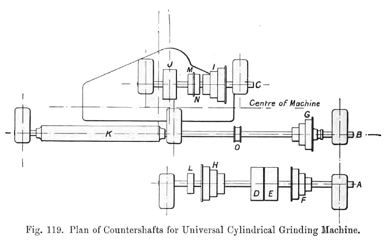
The initial feed pulley I F P receives its motion from the counter shaft B, fig. 119, and this is transmitted through the change feed pulleys C F P and the gearing inside the bed B to the table slide S T by means of a rack and pinion, figs. 117 and 118.
The three countershafts are seen in plan fig. 119; the initial countershaft A receives its motion on the fast and loose pulleys D E from the main shaft. The cone pulley F drives on to the corresponding pulley E, thereby giving motion to the shaft B; on this shaft is the drum K which drives down on to the headstock H W, fig. 117; the length of the drum K is sufficient to allow for the whole traverse of the table. The cone pulley G is provided with a clutch, so that the work may be stopped for gauging or testing without the necessity for stopping the whole machine. The cone pulley H gives motion to cone pulley I, thereby rotating pulley J, which drives down to the pulley on the headstocks G H, fig. 117, thereby rotating the emery wheel spindle. The small flanged pulley 0 upon the middle counter-shaft B drives down to the initial feed pulley I F P, fig. 117. It is advisable to run the pump at a uniform speed, and this is accomplished in the following manner, namely: —The pulley L seen on the first countershaft A (which is always rotating at the same speed) drives over to the flanged pulley M on shaft C; this pulley M is bushed with a bronze bush, and runs loosely between two collars placed upon the shaft C; it will therefore be seen that whilst the countershaft C may have its speed varied, the flanged pulley M will always be rotating at one regular speed, as it is independent of the shaft C, running loose thereon. On the other side of the flanged pulley M is pulley N, which drives down to the pump pulley P, fig. 117, thus ensuring the speed of the pump, and yet allowing of the countershaft A being placed in any convenient position by means of the flanged double pulley M N.
The Steady Rest.—The steady rest is often useful as a support for special kinds of cylindrical work whilst being ground. For instance, if a long shaft or spindle has to be ground and finished perfectly parallel and true, it would necessarily be run on dead centres in the ordinary manner, but owing to its great length in proportion to its diameter, it may not of itself be sufficiently stiff to withstand the pressure due to the cutting action of the emery wheel without a certain amount of chattering or springing, but if it is supported by a steady rest it will be perfectly steady and will run true during the grinding. Again, suppose the machine is grinding the centre hole in the end of a lathe spindle, and the use of the tailstock centre is dispensed with, the usual plan is to chuck the tail end of the lathe spindle in a universal chuck and to place the end to be ground in a steady rest, so as to allow of the small emery wheel being in a position for grinding the hole. A steady rest may be stationary or sliding as required by circumstances. One form of steady rest (a three pin stationary one) is shown at 3 P S in fig. 117. The method of applying these steady rests is practically the same for grinding as for ordinary metal-turning operations.
In the first example given, that of a long shaft, the shaft is first threaded through the steady rest, next placed between the head and tail stock centres, and then the three pins are adjusted so as to support the shaft without giving rise to undue friction; in the second example, the tail end of the lathe spindle would naturally run true, as the universal chuck is a self-setting true chuck. The other end of the spindle is at first supported upon the grinding machine tailstock centre to keep that end of the lathe spindle true; then after the steady rest has been carefully set up to support that end, the tailstock centre is drawn back so as to allow of the internal grinding being effected. If an independent chuck is used for carrying the tail end of the spindle, its four jaws must be set to allow of the spindle running perfectly true previous to fixing and adjusting the steady rest; the universal chuck, however, is nearly always preferred, owing to its automatic action and the readiness with which the cylindrical work can be clinched. |
|
 1903 H. W. Ward & Co., Universal Cylindrical Grinder
 1903 H. W. Ward & Co., Universal Cylindrical Grinder (Top View)
 1903 H. W. Ward & Co., Universal Cylindrical Grinder (Countershafts)
|
|