|
Title: |
1903 Article-H. W. Ward & Co., Cutter Grinder |
|
Source: |
Emery Grinding Machinery, 1903, pgs. 136-138 |
|
Insert Date: |
12/3/2015 7:33:35 PM |
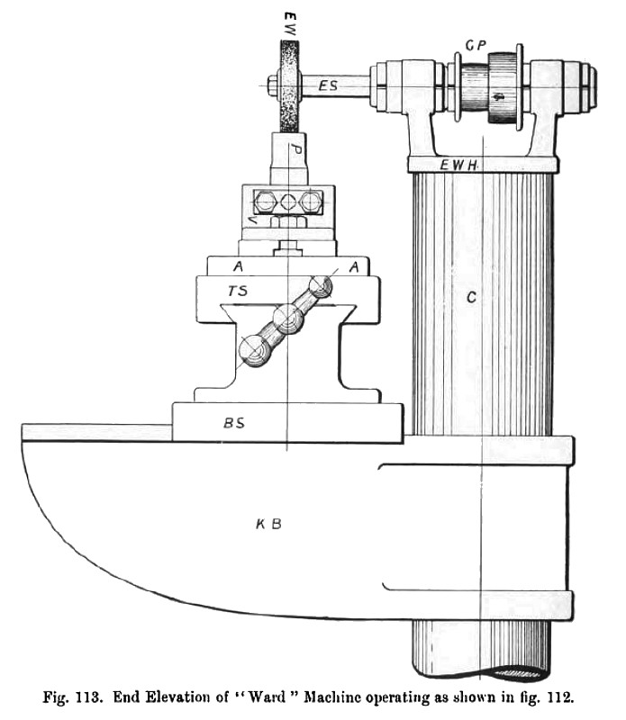
Another example of a machine for cutting-punch grinding is illustrated by the plan and elevation in figs. 112 and 113: the punch is for cutting out a portion of a cycle pedal; the knee bracket K B has been lowered down the column C sufficiently to permit of the punch face being brought directly under the emery wheel; the punch is held by its shank in the vice V, and the top slide T S is worked alternately backwards and forwards under the emery wheel, the bottom slide B S being moved from time to time so as to make the emery wheel operate upon another portion of the punch face. Many varieties of both large and small cutting punches and beds may be ground with the machine in this position.
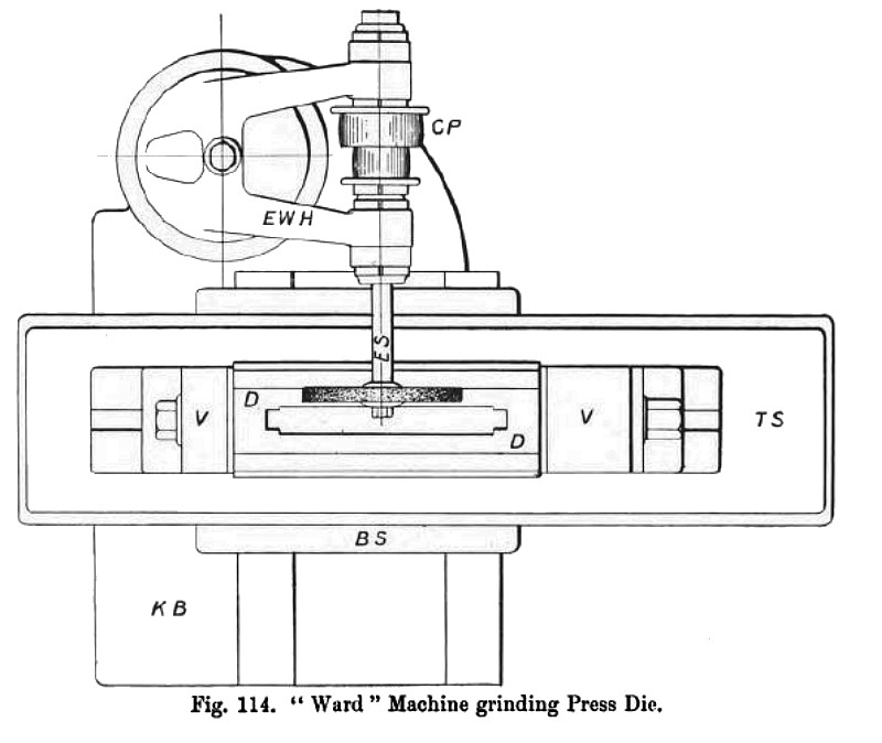
Fig. 114 shows a large cutting bed held between the jaws of a screw vice whilst its top cutting edges are being sharpened by the emery wheel operating upon its top face or surface; the machine is fixed in the same position as is indicated in figs. 112 and 113. |
|
 1903 H. W. Ward & Co., Cutter Grinder
 1903 H. W. Ward & Co., Cutter Grinder
|
|