|
Title: |
1903 Article-H. W. Ward & Co., Cutter Grinder |
|
Source: |
Emery Grinding Machinery, 1903, pgs. 128-134 |
|
Insert Date: |
12/3/2015 7:20:11 PM |
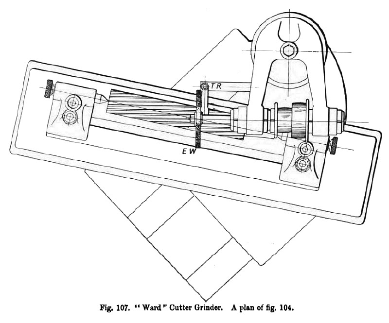
A plan of the cutter grinding head is shown at fig. 107, in which is seen the adjustable table and the headstocks holding a long spiral cutter which is being operated upon by the emery wheel E W. The former T E places the tooth in position and keeps it there whilst the emery wheel does its work; this is really a plan of the work as seen in tig. 104, and explained when reviewing the action of that figure. It will also be noticed in the plan fig. 107 that the axis of the grinding spindle is set in line with the spiral.
Grinding Press Tools.—In reviewing the ancient and modern methods of tool grinding in Chapter I., several kinds of what are known as ordinary metal cutting press tools were mentioned, besides an indication of the extensive varieties of shapes, forms and classes of cutting tools that come under the classification of press tools; in fact, it is questionable if any other industry opens up so many inducements for speculative ideas, or creates so much inventive thought as do the various branches of sheet metal working. It will therefore be apparent that it has not been an easy matter for makers to design a grinding machine suitable for dealing with these very varied kinds of peculiarly shaped tools. The difficulties are not so much in performing the actual grinding operations, as in providing suitable means for holding the varieties of tools in proper position whilst the tool is being operated upon by the emery wheel. These difficulties, however, have been overcome in many instances, at comparatively small cost, by adding extra attachments, whilst in other cases they have been correspondingly expensive; some of these attachments are in the form of chucks and vices, and are illustrated herewith.
It may be noted here that the universal cylindrical grinding machine of the ordinary standard type, illustrated and described in the latter part of this chapter (figs. 117 to 119), can be used for grinding certain varieties of cylindrical press tools, both externally and internally; and in works where this type of machine is installed, it is often used for the purpose of grinding cylindrical cutting-out punches and beds. A machine of this kind would find constant employment in a small arms ammunition or similar works, where large quantities of cylindrical punching and drawing tools are used.
Again, a surface and angle grinding machine would perform many operations with convenience that would be difficult to manage upon a universal cylindrical grinder, so that in works where both these machines were installed, they could be jointly worked with a fair amount of success, the one doing cylindrical cutting and drawing tools, the other dealing with the surfaces and angles of flat-topped cutting beds and their beveled edges, or grinding the cutting faces of square, rectangular or similar cutting punches. The same observation applies to many other machines illustrated in this work; that is to say, on many of the special machines a few kinds of press tools may be ground with a little scheming, but considering that it would be necessary to provide several machines, each of different design, to be able to manage all the tools in the press shop, their cost would more than counterbalance the advantages they would provide.
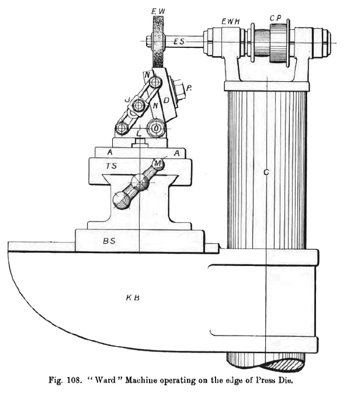
It will therefore be understood that one machine must be provided to meet the whole requirements of the shop. A grinding machine, to be thoroughly useful and successful on press tool work, must of necessity be capable of performing grinding operations in many directions, either vertically, horizontally, or at any intermediate angle. Hence it is advisable to construct the emery wheel headstock so that it will be capable of making a complete revolution in a horizontal plane. The table slides must be designed for giving motion both to and from the emery wheel headstock, and be capable of moving backwards and forwards in front of the emery wheel in a transverse direction. The table must also be provided with means by which it can be raised or lowered through a reasonable height in relation to the emery wheel head. A swivel table should also be provided. The machine illustrated in figs. 108 to 116 has been designed to give these movements. When such a machine is provided with the necessary fixtures or attachments, in the shape of work heads, chuck and vice for holding the tools, the varieties of tools, both punches and beds (within the limits of
the machine), that can be ground thereon, are so numerous that it would seem to justify the name Universal Press Tool Grinder being given to the machine. It is true that there may be an occasional special tool requiring to be ground that might present some little difficulty, but seeing that this is likely to occur in any other department of grinding, it need not be taken into account.
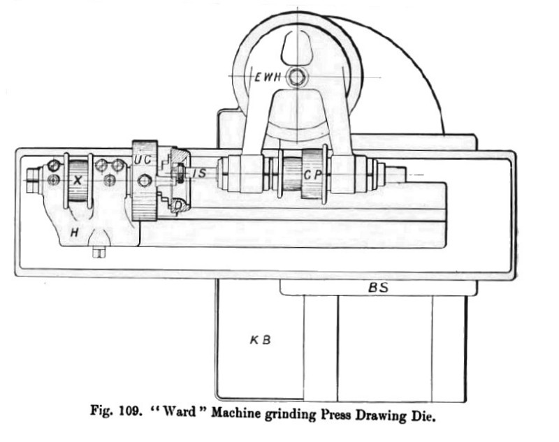
Referring to fig. 108, which is an end view of the press tool grinder, the emery wheel head E W H carries the external grinding spindle E S and the two-speed cone pulley C P. The column C carries the knee bracket K B. The bottom slide B S can be traversed either towards or from the column as desired by means of screw and hand wheel (not shown in the figure). The top slide T S can be traversed in either direction at right angles to the motion of the bottom slide B S by means of the handle M. The swivel table A can be arranged to swivel 10 degrees or more as desired in either direction; it carries a special chucking device used for holding cutting-out beds whilst being ground upon their bevelled edges; this device consists of a base plate L and a receiving plate N N, these two plates being hinged at 0. The cutting-out bed D is held in position on the receiving plate N by means of the pin It. A double set of slotted links are provided for moving the receiving plate N so as to place the edge of the bed D at any desired angle; this angle is obtained by loosening the pin J and telescoping the links. In the figure the emery wheel E W is grinding one angle of the bed. The machine is shown in plan at fig. 109, and is set up for grinding the hole of a cupping or drawing die D; the emery wheel head E W H has been moved through 90 degrees, so as to bring the small internal grinding spindle into proper position to grind the die; this die D is held by the universal chuck U C, the chuck being mounted upon the headstock H, and driven by the pulley X. |
|
 1903 H. W. Ward & Co., Cutter Grinder
 1903 H. W. Ward & Co., Cutter Grinder
 1903 H. W. Ward & Co., Cutter Grinder
|
|