|
Title: |
1903 Article-H. W. Ward & Co., Cutter Grinder |
|
Source: |
Emery Grinding Machinery, 1903, pg. 125 |
|
Insert Date: |
11/29/2015 8:56:16 PM |
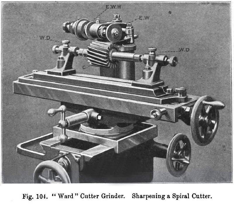
Fig. 104 represents a machine as set up for grinding a spiral cutter. The emery wheel E W is operating upon the top of the cutter C; the cut is put on vertically by means of the lower hand wheel seen at the right-hand side of the machine. The point of the former being placed immediately at the back of the tooth that is being ground, the operator, with his right hand upon the hand wheel at the end of the table, winds backwards and forwards, whilst, with his left hand on the cutter, he keeps the cutter tooth bearing on the former, thereby giving the spiral movement necessary. The former consists of a piece of spring steel, so that after one tooth has been sharpened the cutter is moved backwards, and the spring steel former clicks into position on to the next tooth like a ratchet.
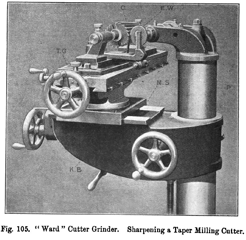
Fig. 105 shows the machine sharpening a taper milling cutter, the teeth of which are straight. In this arrangement it will be noticed that the knee bracket K B has been raised higher up the column so as to bring the centre of the cutter level with the centre of the emery wheel, the reason for this being that the set-over of the table for taper grinding is in a horizontal direction. The table will swivel to the extent of 10° in either direction. It has a fine screw adjustment graduated to half degrees and to inches per foot. The cut is made in a horizontal direction by the hand wheel on the extreme left of the machine.
In fig. 105 the former is placed upon the table; in fig. 104 on the head.
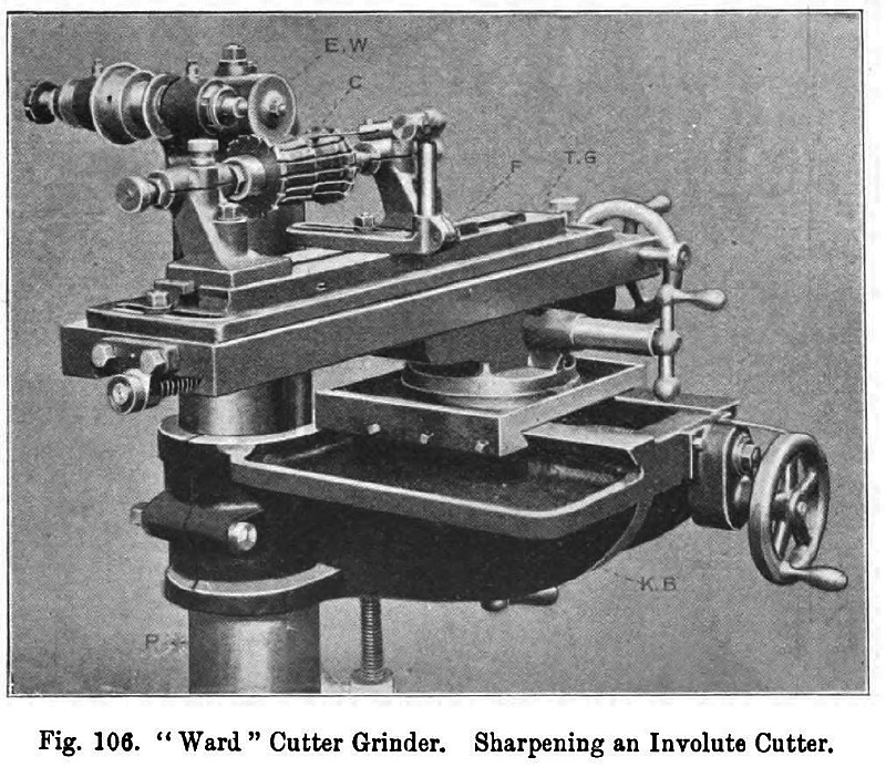
Fig. 106 represents an involute milling cutter being ground with a dish or cup wheel E W, the face of the dish wheel operating upon the face of the tooth instead of the top. This is a case where it is absolutely necessary that the emery wheel spindle should be at right angles to the axis of the cutter that is being ground. The former in this case is placed at the back of the tooth, it being impossible to place it on the same side as that on which the emery wheel is operating. |
|
 1903 H. W. Ward & Co., Cutter Grinder
 1903 H. W. Ward & Co., Cutter Grinder
 1903 H. W. Ward & Co., Cutter Grinder
|
|