|
Title: |
1903 Article-James J. Guest & Co., Cutter Grinder |
|
Source: |
Emery Grinding Machinery, 1903, pg. 118 |
|
Insert Date: |
11/24/2015 12:42:48 PM |
The manner in which the correct clearance is ground upon cutters may be traced by referring to figs. 98, 99, 100 and 101. Most cutters are ground by the method shown in fig. 98, from which it will be seen that the grinding spindle G S is canted upwards when in this position, and that the top of the worktable T is horizontal. The tooth of the cutter to be ground is located by the edge E of the tooth rest E, which works upon the surface T. This edge E is at the same height above T as the centre C of the work is, and consequently the tangent, at the point of the tooth being ground, to a circle enveloping the cutter, is vertical for all sizes and shapes of cutters, therefore the grinding wheel W, which is a cup or dish wheel, by being pitched over, puts on a clearance, which is the same for cutters of all diameters, as illustrated by the dotted circles A A and B B, which indicate cutters differing in diameter from that which is being sharpened. Fig. 99 shows a face cutter being ground by this method. It does not matter at what height on the wheel the cutter is ground, but it is usually considered best to set the table low, and to grind nearly at the bottom of the wheel. The clearance produced is flat and the edge smooth, both of which are advantages.
Sometimes, however, it is best to grind a cutter on the edge of the wheel as indicated in fig. 100. In this case the operation is as follows:—Place the tooth rest J on the inclined plane K, fixed to the wheel headstock, and clamp it so that its working edge H is just outside the wheel as in fig. 100. Place the tooth rest E (fig. 98) upon the table T as in fig. 100, and adjust the table until the edges H and E meet. The table is then correctly set, and any cutter is ground to the correct clearance, which, by arrangement, is to be the same as that obtained by the method given in the description of fig. 98. In fig. 100 the circles A A and B B, indicating cutters, are drawn as before to show that this is so. The tooth rest J is of peculiar construction (see fig. 101); the blade Z is fitted to the body J by a circular arc, having its centre at the middle of the edge H. When a spiral cutter is to be ground, the blade is adjusted to fit the spiral of the cutter, but this adjustment does not move the centre of the blade, so that the same constant clearance is produced on spiral as on other cutters.
Fig. 102 represents the operation of grinding the side of a slitting saw hollow. These saws, which are used extensively on metal work, are usually ground hollow after being hardened and tempered, but sometimes they are ground after hardening, but before tempering. |
|
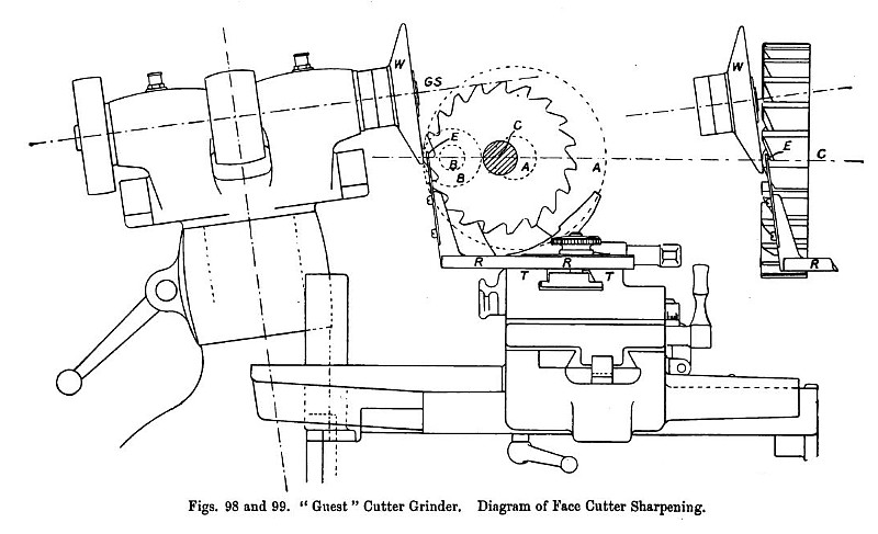 1903 James J. Guest & Co., Cutter Grinder (Diagram of Face-Cutter Sharpening)
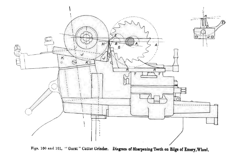 1903 James J. Guest & Co., Cutter Grinder (Diagram of Sharpening on Edge of Emery Wheel)
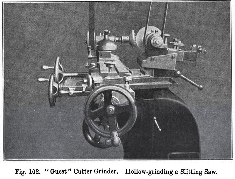 (Hollow-Grinding a Sltting Saw)
|
|