|
Title: |
1903 Article-James J. Guest & Co., Emery Grinder |
|
Source: |
Emery Grinding Machinery, 1903, pgs. 104-108 |
|
Insert Date: |
11/23/2015 11:38:04 PM |
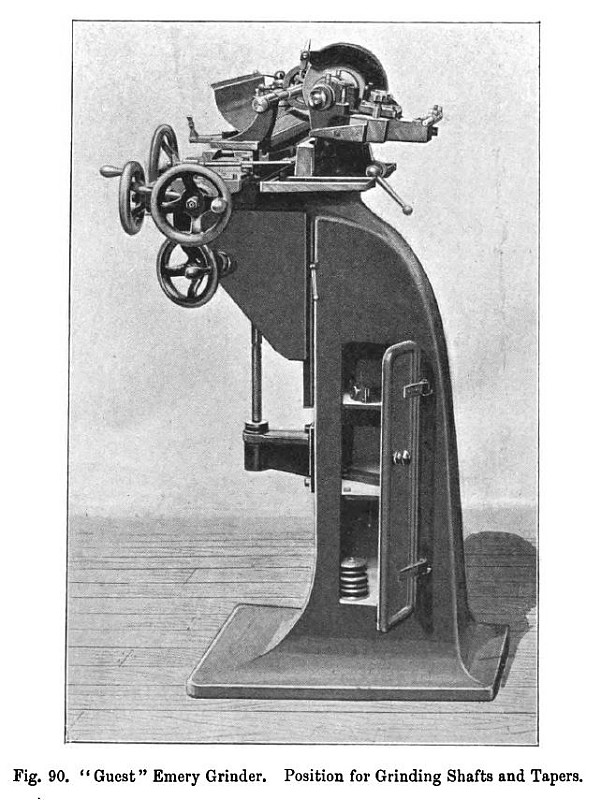
The Guest Universal Cutter Grinder
The combined universal cutter and grinding machine (fig. 90) is known as the "Guest." It is especially suited to the requirements of general manufacturers, as, in addition to dealing with cylindrical internal and external work rapidly and accurately, it will conveniently grind cutters, reamers and similar tools. This machine is a great time-saver for the following reasons: (1) the style of grinding can be changed almost instantly; (2) as water can be freely used in ordinary grinding, the temperature is not raised sufficiently to interfere with the accuracy of the work; (3) the correct clearance of the cutters is automatically ensured, so that no time is spent in calculating and measuring.
General Description—The grinding spindle is carried in a head which revolves in a bearing in the body. It is so arranged that, whatever its position, the belt is always equally tight and the spindle therefore runs smoothly; it avoids the jar incidental to automatic tighteners, and the waste of time involved in hand adjusted tighteners. The tightener requires adjusting only a few times in a year, so that an endless belt can be used, which does not give the jar occasioned by the joint of a laced belt running at a high speed.
The wheel guards are designed for almost instantaneous removal and replacement (when necessary), the time required being so brief as to afford no excuse for an operator neglecting their use.
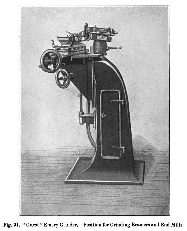
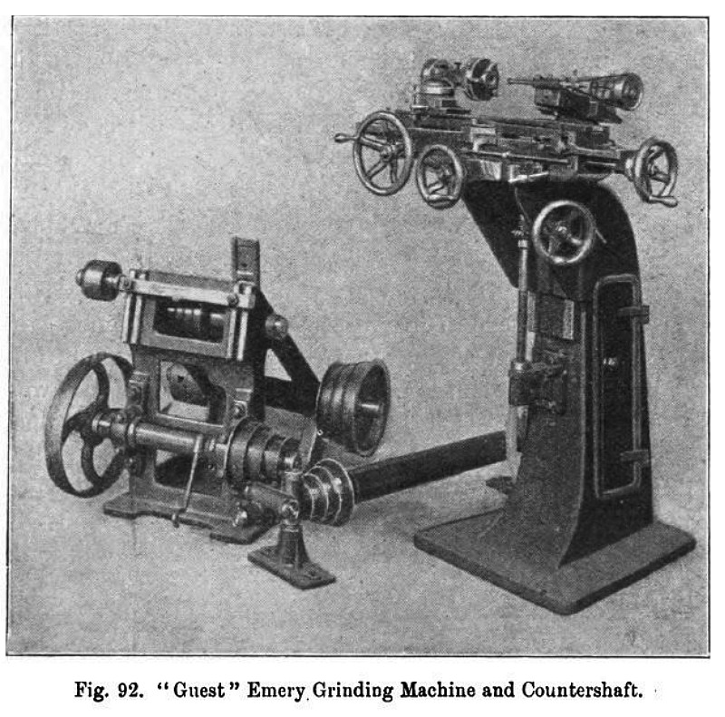
For ordinary grinding shafts, tapers and suchlike work, the head is used in the position shown in fig. 90. A quarter turn in either direction brings it into the position shown in fig. 91, used in grinding almost all cutters, reamers, end mills and taps. A further quarter turn brings the internal grinding spindle to the working position indicated in fig. 92. The internal spindle is driven from the ordinary grinding spindle by an open belt; this device of a revolving head instead of the knee enables the machine to be placed in line with others, and also allows of the operator always working from the same side, so that the light always comes from the same direction, which, by proper arrangements, will be the most suitable one. This is a very important point when accurate grinding is needed.
The head can be quickly, easily and accurately set to any desired position; and owing to the stability of the machine, a deep stiff knee can be used, which renders it much easier to produce accurate work. On the other hand, it is very difficult to adjust the head to the right position in other machines when the knee with all its adjuncts—saddle, main slide, work-table, headstock, etc.—has to be moved round a column.
The use of water allows of highly finished work being done rapidly and accurately. Two shields of sheet metal, made to move with the headstocks so as always to be in position, effectually prevent any abrading material from being carried by water through the slides on to the top table; for should its surface be abraded, the true alignment of the headstocks is very soon interfered with.
External Work.—Fur grinding shafts, arbors, tapers and other external work, the machine is used in the position shown in fig. 90, and the work, held between the centres or carried by one headstock, is driven from the overhead drum. The table should be set at the height indicated by the gauge, because, in quick work, the cross feed screw must size the work precisely. The grinding spindle need not be parallel with the main slide; indeed, when nearing a shoulder, it should be somewhat inclined. The emery wheel should be trued with a diamond tool when necessary, and the rod containing the diamond should be placed in a holder mounted upon the machine table and traversed by the rack feed.
Fig. 90 represents the machine when grinding a parallel shaft. To grind tapers, the swivel table is set over so that it is not parallel to the main slide.
Internal Work.—For internal grinding the head is undamped and a half turn made to the position shown in fig. 92. The pulley and belt for driving the small spindle is placed in position. As in external ordinary grinding, it is not necessary that the head should be set exactly square with the main slide, but the knee should be set at the correct height. The work is Cutter Grinding on "Guest" Machine.—For grinding most cutters the grinding head of the machine is set in the position indicated in fig. 91; that is, the wheel shaft is inclined upwards at the needed angle of clearance, the top of the work-table is horizontal, and the axes about which the work-table and top of swiveling headstock rotate are vertical. |
|
 1903 James J. Guest & Co., Emery Grinder
 1903 James J. Guest & Co., Emery Grinder
 1903 James J. Guest & Co., Emery Grinder
|
|