|
Title: |
1903 Article-William Muir & Co., Steel Roll Grinder |
|
Source: |
Emery Grinding Machinery, 1903, pgs. 70 |
|
Insert Date: |
11/20/2015 8:43:12 PM |
|
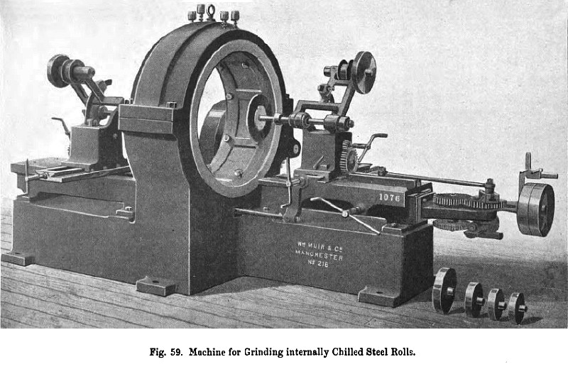
The large grinding machine (fig. 59) was originally designed for grinding internally interchangeable chilled steel rolls 26 inches in diameter by 15 inches broad (fig. 60), the hole through the rolls being in the form of a double cone, the apexes of which are in the centre of the roll. These chilled rolls are used for quartz-crushing machinery. The machine represented in fig. 59 weighs about 98 cwts. It is suitable both for dealing with the chilled rolls and for grinding inside steel rings and cylindrical linings, but the external diameter must not exceed 27 inches, as no article with a larger diameter can be "chucked" as indicated by fig. 59. The machine consists of one large casting, which forms right- and left-hand beds, with the driving headstock in the centre. The slides and traversing carriages are mounted upon the upper surfaces of the beds, and driven by an adjustable crank, connecting rod, compound worm and wheel gear, fast and loose pulleys; the carriages are coupled together by a strong tie rod, which can be disconnected so as to allow the left-hand carriage to be worked by hand if required. The self-acting traverse is alike for each carriage, so that they work simultaneously when coupled together, the amount of traverse being regulated from the crank. The position of the grinding wheel is obtained by the adjustment of the connecting rod in the T slot on the left - hand carriage, and a quick hand movement can be given to each carriage by handle, pinion and rack. A transverse grinding headstock is mounted upon each carriage and worked on opposite sides with an adjusting screw. A disengaging nut allows of the rapid movement of the headstock by rack and pinion, so as to clear the "chuck" when putting in or taking out the work. The driving is direct from countershafts, compensating frames being employed on each spindle head to keep the belts in tension. There are three changes of pulleys to suit the various diameters of emery wheels; these spare pulleys are seen in the right-hand bottom corner of fig. 59. The Alfred Muir's patent coupling used on the spindles readily secures and releases the mandrills of the emery wheels. The chuck seen in the centre of the machine bed is driven by single speed pulley, pinion and spur gearing, working in the shell cap, this driving mechanism being at the back of the machine. The work to be ground is fixed in the chuck by sixteen jack screws, eight on each side; some of these jack screws are clearly seen in the illustration. |
|
 1903 William Muir & Co., Steel Roll Grinder
|
|