|
Title: |
1921 Article-Triplex Machine Tool Corp., Combination Bench Lathe, Milling & Drilling Machine |
|
Source: |
Machinery, V28, Dec 1921, pg. 323 |
|
Insert Date: |
11/15/2015 9:50:59 PM |
Triplex Combination Bench Machine
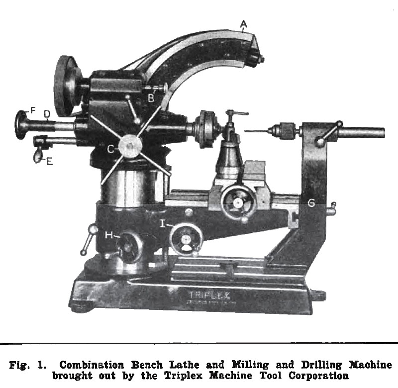
A combination bench type of machine which may be used for all operations done on regular bench lathes, millers, and drilling machines, thus reducing the amount of equipment ordinarily required in tool-rooms, has been developed by the Triplex Machine Tool Corporation, 18 E. 41st St., New York City. One of the unique features of this machine is the method of mounting the spindle head. It will be seen from Fig. 1 that the spindle 'head is mounted on an arm A. which has the form of an arc and which is graduated in one-half degrees to facilitate setting the head in any angular position between the horizontal and the vertical. The head may be clamped in position by tightening a single nut, and is balanced by means of a counterweight within the hollow column. The spindle is driven by a motor, which is attached directly to the head, and which, consequently, maintains the same position relative to the head regardless of the position of the latter. The drive to the head is by means of a belt running on two-step pulleys. The motor has a rating of ¼ horsepower, is reversible, and of the constant-speed ball-bearing type, its speed being 1750 revolutions per minute. As the motor is reversible, either right- or left-hand tools may be employed.
Six spindle speeds are obtainable, the lowest of which is 90 and the highest 1150 revolutions per minute. These changes in speed are obtained by operating handle B which controls three shifting gears. The spindle can be fed a distance of 3 inches by turning the spider wheel C, and can be locked at any point by means of a clamping handle located above the spider wheel. The possibility of extending the spindle is particularly advantageous when some difficult milling and lathe work is being done.
The spindle is always fed by hand except when cutting threads, in which case it is fed by a master screw D, which engages a nut segment attached to handle E. The engagement is effected by swiveling handle E. The spindle is fed forward as it revolves, due to the engagement of the threads on the master screw and segment. At the completion of a cut, the nut segment is automatically disengaged by the beveled edge on the hub of hand-wheel F. Internal threads can also be cut in a similar manner when a proper threading tool is used. Either a faceplate, collet, or chuck may be attached to the front end of the spindle.
The bed of the machine swivels on the column, and may be swung to one side so that high work may be placed on the base, which is provided with three standard T-slots for bolting down the work. In Fig. 1 the outer end of the bed is supported by an upright member G, which can be removed when not needed. This upright is provided at the upper end with a socket in which may be inserted a center for holding work between centers, or the shank of a chuck as shown. The bed is raised and lowered on the column by rotating hand-wheel H, and the carriage is fed longitudinally on the bed by hand-wheel I. The transverse feeding of the carriage slide is accomplished through the operation of the hand-wheel on the front of the carriage. The various hand-wheels are provided with dials graduated to 0.001 inch. The carriage can be clamped in any longitudinal position, and the bed in any angular position. By swinging the bed the required amount, any degree of taper, in either direction, can be turned on work. Graduations on the column bearing of the bed facilitate these settings.
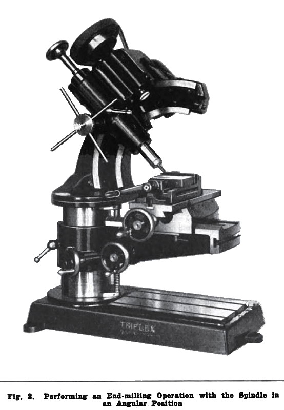
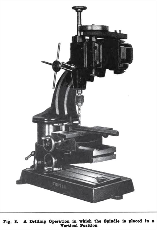
Milling operations can be performed by mounting a cutter on an arbor supported between the spindle and the tailstock center, or end-milling operations can be accomplished by inserting the cutter in a spring collet in the spindle, as shown in Fig. 2. The spindle head is shown in an angular position on its arm in this illustration. Fig. 3 shows the head in a vertical position, the machine being used as a bench drilling machine. A Jacobs drill chuck having a capacity for drills up to ½ inch in diameter is supplied. Some of the specifications of the machine are as follows: Longitudinal feed of carriage. 10 inches; transverse feed of carriage slide, 6 inches; vertical feed of bed, 4½ inches; maximum swing over carriage, 8 inches; maximum swing over bed, 14½ inches; maximum center distance, 14 inches; maximum height with spindle In vertical position, 43 inches; weight of machine, about 450 pounds; and bench space required, 16 by 25 inches. |
|
 1921 Triplex Machine Tool Corp., Combination Bench Lathe, Milling & Drilling Machine
 1921 Triplex Machine Tool Corp., Combination Bench Lathe, Milling & Drilling Machine (Angular Positi
 1921 Triplex Machine Tool Corp., Combination Bench Lathe, Milling & Drilling Machine (Vertical Posit
|
|