|
Title: |
1920 Article-Hanson-Whitney Machine Co., Vertical Tool & Die Shaper |
|
Source: |
Machinery, V26, Mar 1920, pg 669 |
|
Insert Date: |
11/9/2015 1:55:13 PM |
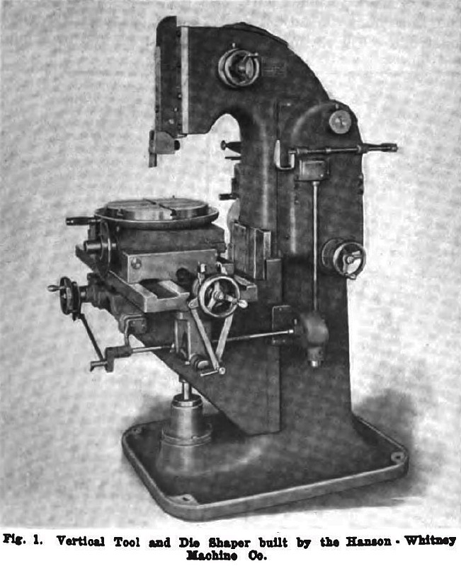
To meet modern requirements in the manufacture of fine tools, the Hanson-Whitney Machine Co., Hartford Conn., has recently started to build a vertical tool and die shaper. This machine is especially suited for use in making punches and dies of various types, which are widely used in the production of parts for electrical appliances, typewriters, adding machines, clocks, watches, etc. Although it is comparatively small size, sufficient range is provided to enable large sized dies to be swung in all directions without interference; on the other hand, it is claimed that small tools for precision operations can be used with the utmost sensitiveness. In working out the design of this machine, especial attention was given to the development of means for accurately controlling all of the functions, so that the most refined work can be done under conditions that enable the operator to depend upon the machine holding his work within close limits. The ram travels very rapidly, thus increasing the rate of output.
Liberally proportioned bearings support the vertical slide or ram and the knee is rigidly secured to the column, being guided at the center by a dovetail and locked at the edges with square locks. The working slides are furnished with narrow guides, and for the size of the machine, they have a large range of action.
A combination of flat and tapered bearings supports the rotary table which has an indexing mechanism of the same type that is employed on a universal milling machine. An automatic feed is provided for both slides, and the feed in all cases occurs on the return stroke of the ram. There are several features of the design of this machine which are believed to be entirely new. Among these mention may be made of the following:
Provision is made for adjusting the length of stroke, regardless of whether the machine is running or at rest, and such adjustments can he made with equal facility under either condition. Variations in the length of stroke are accomplished by a hand wheel shown at the side of the column just back of the ram, the mechanism used for this purpose being of simple and durable construction. When the machine is stopped, the ram will automatically come to rest at the top of its stroke. The handle shown on the right-hand side of the column is pulled toward the operator to start the machine and this handle is pushed back into the position shown in Fig. 1 to bring the machine to rest. No matter when this is done the ram will stop at the end of its up stroke. On the back stroke, the tool positively recedes from the work and on the down stroke it is returned to the operating position. In this way no trouble is experienced through dragging the edge of the tool over the piece that is being machined.
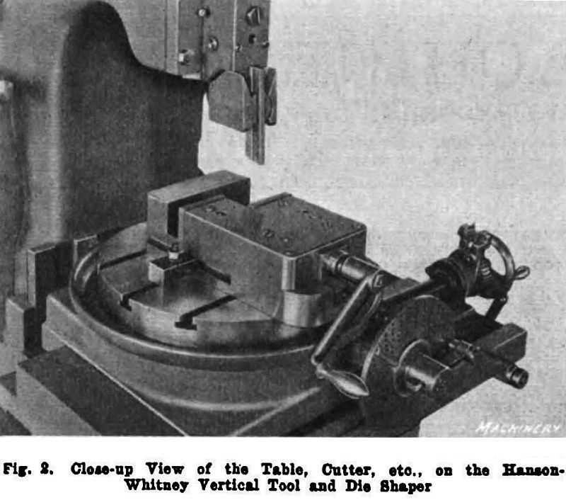
By examining the construction of the tool-holder, it will be seen that there is no set-screw or any other projecting member to prevent the ram from clearing the work. In other words, a long overhang of the tool is not necessary when planing the outside of a piece and when planing on the inside of a die or similar part, it is only necessary to have the overhang of the tool as long as the cut to be taken. The standard tool made with a clearance as illustrated in Fig. 2, and when sharpened it only needs to be ground at the end. Various shaped tools can be made to meet the requirements of different jobs such as square-nose, round-nose, diamond-point, etc. All working surfaces, in connection with the clapper mechanism, are made of hardened and ground steel. In addition to the rotary motion of the table, it can also be tilted so that when making dies, where a clearance is desired, this result can be easily obtained, a segment graduated in degrees indicating the amount of taper that is necessary. Feed-screws on the slides have the usual micrometer dials graduated to 0.001 inch.
Three changes of speed are provided in the driving mechanism which receives power from a tight and loose pulley on the left-hand side of the column. No countershaft is necessary, as the machine can be driven directly from the main line-shaft. An interlocking device in the speed change mechanism enables shifting to be done without danger of injuring the gears. The fast driving pulley may be running constantly and a speed will be engaged by the handle at the right-hand side of the machine, of which mention has already been made, which engages the ram motion through an expanding friction clutch without shock or noise. About one-half way down on the right-hand side of the column there is a hand-wheel that can be engaged with the mechanism when the machine is at rest, to provide for turning the machine by hand while setting up a piece of work to make sure that there is no interference. The knee may be adjusted relative to the positioning of the stroke. Fig. 2 shows a work vise of substantial construction, which is made for holding small pieces of work, the design of this tool being distinguished by the fact that it has two gaps, one of which is capable of opening up to 2 inches and the other up to 4 inches. This vise is finished all over and has hardened and ground jaws A tool-holder for securing small tools and other work on the machine is also made to special order.
Dies of the types which are machined on this vertical tool and die shaper are finding a steadily increased application in industrial plants that are engaged in the manufacture of a diversity of products. |
|
 1920 Hanson-Whitney Machine Co., Vertical Tool & Die Shaper
 1920 Hanson-Whitney Machine Co., Vertical Tool & Die Shaper (Vise)
|
|