|
Title: |
1859 Article-Stover Machine Co., Molding Machine |
|
Source: |
Scientific American, Volume #1, Issue 25, 17 Dec 1859; pg. 393 |
|
Insert Date: |
5/28/2014 1:27:53 PM |
STOVER'S MOLDING- MACHINE.
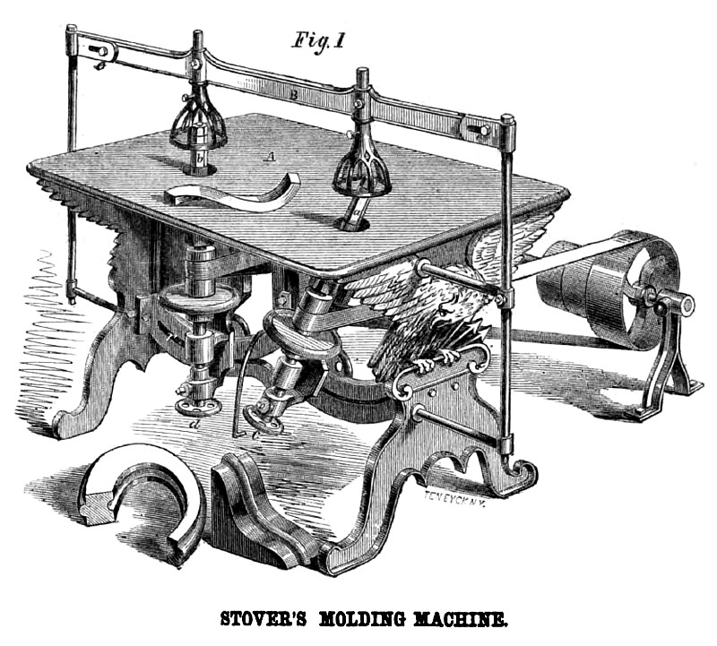
There is no machine which produces to great a variety of effects, by a few parts, as the molding machine; and the one which we here illustrate, by the simple device of inclining the cutter head at various angles, in addition to the almost endless variety of results usually produced, is able to cut surfaces of all conceivable forms, and is thus peculiarly adapted for fashioning ship-timber, furniture and molder's patterns, and for various other purposes. Stover's machine has also other peculiarities, which we will endeavor to make plain with the aid of the annexed engravings.
A plane table, A, is supported on a strong iron frame, and has passing through it the swiftly-revolving shafts, c and d, which carry the cutter heads, a and b, upon their upper ends. As these shafts and cutter heads are similar, a description of one will suffice for both: The cutter head, b, then, has firmly secured, at two opposite sides, two steel cutters with the edges parallel to the length of the head, and projecting n. very little from the surface, in the manner of a plane iron. Between the cutters and the table is a smooth surface for a pattern to press against; the pattern being previously fashioned in the form desired, the "stuff" to be cut is fastened upon it and pressed against the revolving cutters, which, of course, rapidly plane away the stuff, and give it the lame form as the pattern, as it is carried along with the pattern in contact with the guide. The shaft, d, is supported on a step at the bottom, and runs in two journal boxes, the top one of which is hung on pivots, and the bottom one is fastened by a set screw in any part of the curved slot, r, so that the shaft may be inclined at any desired angle, as shown by the shaft, c. For protecting the hands of the operator from being wounded by the revolving cutters, the cast-iron basket-work shields are brought over the cutters. These are fastened by set screws to the bar, B, which is supported by rods also held by set screws, so that the height of the shields may be adjusted at pleasure. The bar, B, is fastened at its ends to the two pieces which support it on the rods, by means of screws in elongated holes, so that it may be turned up to remove the shields out of the way in changing the cutters; or the whole apparatus may be removed by drawing the rods from their supporters. When the inner edges of oval picture frames are to be carved, or other work done in which these shields would be in the way, the shield represented in Fig. 2 is substituted. The shield, C, is screwed upon the cutter head at any desired height from the table corresponding with the thickness of the stuff, and is held in place by a nut which is secured tightly upon it; the collar, k, serving to hold the shield in its position concentric with the shaft.
The guide for the pattern is attached to the upper journal box, and the revolving shaft passes through it loosely, so that the guide does not revolve, and the usual wear to the pattern from this cause is prevented. As the belt which drives the shaft constantly draws it against one side of the journal boxes, and thus wears one side of the box more than the other, the shaft is thus removed from its position concentric with the guide: to obviate this, the journal box is bushed with a crescent-shaped lining of metal, the thick portion of which is placed at the side of the greatest wear, and which may be forced out against the shaft by set screws as it is worn away.
Fig. 3 represents the form of that portion of the cutter head to which the cutters are secured, with the curved groove or recess for the shavings. A cutter for moldings is represented at S, in Fig. 2; the shield being let partly over it by a slot and the wing of the shield acting to regulate the depth of the cut before the pattern is
[graphic] carried in against the guide. Figs. 1, 2, 3, 4, 6, 6 and 7 (next page) illustrate the method of fastening the cutter irons in the head. When long irons are used, they are made double, in the manner of the double iron for the bench plane, in order to make smooth work in cross-grained hard wood; and they are fastened to the head in the mode shown in Figs. 6 and 7. Two straight beveled grooves are made in the collars at the top and bottom; and the double iron, f, being placed in the grooves, a curved steel clamping piece, g g, of spring temper, is pressed very firmly against them by turning the nut, h, and forcing down the collar, i, the bevel in the groove drawing in the ends of the steel clamp, and its curved form causing it to press with great force against the middle of the iron. Fig. 7 shows the position of the pieces before the nut is screwed home, and Fig. 6 afterwards.
The cutter irons are made a very little shorter than the clamps, in order that they may be inclined a trifle edgewise to bring their edges parallel with the cutter head, in case the edges should not be ground exactly at right angles with the end. This mode of fastening the cutters permits them to be made of iron, a matter of great importance in cutters for molding, which must be made with edges of various shapes for fashioning all the numerous styles and sizes of moldings required. As these cutters have to be filed into shape, the use of iron as the principal material in their composition facilitates very much the labor of making them. Of course, it is necessary to face their edges with steel; and this is done in a mode to preserve the edge of steel as the cutters are worn away. When a series of cutters are used, one pair above another, it is necessary to interpose collars between the pairs, and experience has shown that there is great liability in these collars to turn, and thus loosen all the cutters. To prevent this turning, Mr. Stover flattens the screw of the cntter head on two sides, and fashions the holes in the collars to fit this flattened screw, as shown in Figs. 4 and 5. This also brings the cutters Dearer the center, and adapts them to cutting small circles.
When the stuff is first brought in contact with the cutters, before the pattern caches the guide, it is liable to be caught by the cutters, and thrown from the table. To obviate this, a movable clamp (represented in Fig. 8) is provided, one end of which rests upon the table, and the other end, N, is provided with a toothed or serrated jaw, which may be pressed down upon the stuff to hold it firmly in place. For pressing it down, a bar, P, is pivoted to the middle of the clamp, and, passing through a slot in the table, is connected at its lower end with a lever, one end of which rests against the lower side of the table, and the other end is provided with a strap and stirrup for the foot of the operator. The slot extends nearly the whole length of the table, and is crossed by a wider slot at the end, through which the clamp may be dropped, when not in use, upon supporting bars below. The serrated jaw revolves upon a pivot, allowing the stuff to be turned upon this pivot as a center, and the edge or end cut in the arc of a true circle. As the clamp may be placed in any part of the slot, the radius of this circle may be varied at pleasure.
For carving certain warp surfaces for heavy ship-timber, an arrangement is made to feed the timber by a regular and positive motion of the machinery, and, at the same time, to vary the angle of the cutter head, also, by an automatic device. For this purpose, a long screw or worm, so geared to the machinery as to receive a slow revolution, is made to carry the lower journal box along its curved slot by a perfectly regular and very slow motion. As the feed of the timber may be varied at will, it will be seen that this combination enables the operator to cut the edge of a timber, one portion at any desired obtuse angle (within the compass of the curved, slot) gradually bringing the edge up to a right angle, and carrying it down to quite an acute one; or the warp may be reversed from the one here described, commencing with an acute angle and terminating with an obtuse one. Various forms of warp surfaces may also be cut by carrying the stuff wholly or partly around the inclined cutter, leaving the latter stationary at any desired angle. This peculiar feature of this machine—the inclined cutter head—adapts it especially for cutting ship-timber, as well as for carving gun-carriages, fashioning heavy patterns of various forms for castings, and for shaping warp surfaces generally. We are told that the British government has some of these machines in use for carving gun-carriages at their large armories, and that orders have just been received for a number of them for the several navy yards in England. Machines may be seen in operation at the Manhattan Chair Company's manufactory, and at the Empire Works, in this city. The four patents by which this invention is protected are dated, severally, March 11, 1856 (#14,421); May 19, 1857 (#17,343); August 31, 1858 (#21,379) and August 30, 1859 (#25,286). Any further information in relation to the matter may be obtained by addressing the Stover Machine Company (H. D. Stover, president), 13 Platt-street, this city. |
|
 1859 Stover Machine Co., Molding Machine
|
|