|
Title: |
1861 Article-William Jackson, Mortising Machine |
|
Source: |
The Engineer, 27 Dec 1861, pg. 386 |
|
Insert Date: |
10/13/2015 5:01:56 PM |
This invention, by William Jackson of Leeds, consists of "Improvements in Mortising Machine," connecting the hand lever of a mortising machine to the apparatus which carries the cutting tool by means of a link, so as to produce the required vertical motion of the cutter or chisel. The spindle to which the cutting tool is fixed passes through an upright casting, or box, or cylinder fixed upon the spindle. These two parts move together vertically; but the spindle has an independent axial motion, so that the position of the cutter may be altered when required. Into the casing, box, or cylinder a pin which is connected to the upper part of a pendent link enters at the side and has a free motion within it. At the lower end of the link is another pin which enters into and has a free motion within the hand lever. The hand lever moves vertically to actuate the cutter or chisel, and is connected to the framing of the machine by a pin or stud which acts as a fulcrum. When, therefore, the hand lever is raised or lowered a corresponding motion is communicates by means of the link to the casing, box, or cylinder, and consequently to the spindle which carries the cutter. The cutting operations is, therefore, effected by bringing down the chisel by means of the hand lever, and the wood under operation may be moved forward as required by means of the toothed gearing connected with the moveable bed on which the wood is secured.
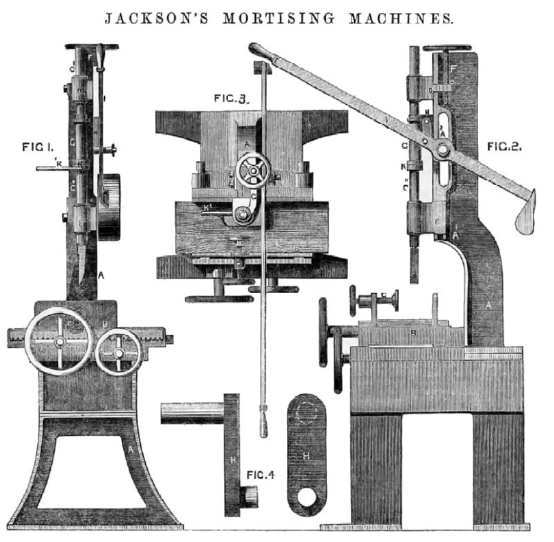
Fig. 1 is a front elevation of the improved mortising machine; Fig. 2 is a side view of the same; and Fig. 3 is a plan view.
A, A, is the frame of the machine; B, the adjustable bed for holding the wood to be mortised; C, the binding or clamping screw for securing the wood on the bed. The lateral and longitudinal adjustments of the bed B are effected in the usual manner by means of the hand wheels, screws, and toothed gearing shown in the illustration; C* is the spindle which carries the cutting tool which is let into the lower end thereof. This spindle slides in adjustable brackets D and E, which are connected together by being bolted to a vertical rod, which insures their simultaneous adjustment in the slot A1 of the framing. The up-and-down movement of these brackets is effected by turning the screw F by means of the hand wheel at its upper end. The screw F takes into a tapped lug on the bracket D, and according to the direction in which the screw is turned the brackets will be raised or depressed, and the accurate adjustment of the parts effected as required. The C* passes through the casing, box, or cylinder G, which has a flat face, and slides against the planed face of the upright framing, and is thereby kept in position. The casing, box, or cylinder G is secured to the spindle C* by being confined between a collar and bush K, so that they may move up and down together, yet at the same time the spindle with its cutter is free to receive an independent axial motion. A pin passes through the removable collar and bush K, and through the spindle C* for the purpose of supporting the spindle in its bracket guides. Into and through the side of the casting, box, or cylinder G a longitudinal hole is drilled, and into this passes a pin, which is connected to the upper end of the link H, which is shown detached and drawn full size at Fig. 4. To the lower end of the link H, is another pin attached to the opposite side of the link, and this pin is secured to the hand lever I; but both pins are free to move within their respective sockets. The hand lever I is fixed to the machine by being bolted in or to a slot A2 in the framing. When, therefore, it is actuated by being moved up or down the link H will impart a vertical motion to the spindle C*, and, consequently, to the cutting tool at the lower end of the same. The lower part of the casing, box, or cylinder G has a vertical hole drilled into it, and into this hole a helical spring is inserted, and a loose plug also enters below the spring. Close to the under surface of the case, box, or cylinder G, an by which the latter is maintained in position is the bush K encircling and fastened to the spindle and on the upper surface of the bush K, two cups or sockets are let into it, and are inclined on one side from the bottom thereof to the surface of the bush, and the inclines of both cups in their relative direction approach each other. When, therefore, the reversing handle K1, Fi. 1 (which is fixed to the bush K), is turned, an axial motion is given to the spindle C*, and when the cup approaches the plug in the vertical socket the nose of the loose plug below the helical spring enters the incline leading to the cup, and is pressed down into it by the helical spring. When it reaches the bottom of the cup the plug is locked, and the further axial motion of the spindle is prevented. This insures the accurate position of the cutter in the spindle C* when its cutting edges require to be reversed to permit of the completion of the mortising operation. When this position is required to be reversed the bush K and spindle C* are again turned, the loose plug passes up the incline and is forced into the socket, where it remains with its nose resting on the surface of the bush until the other cup is brought beneath the plug, when it is again locked in a similar manner as before.
Image courtesy of Grace's Guide |
|
 1861 William Jackson, Mortising Machine
|
|