|
Title: |
1851 Article - Stave jointing machine |
|
Source: |
Scientific American, 27 December 1851, pg. 116 |
|
Insert Date: |
4/9/2017 12:02:04 PM |
STAVE JOINTING MACHINE.
The accompanying engraving is a perspective view of the improved stave jointing machine of Mr. Daniel Drawbaugh, of Cedar Springs, (White Hill P. 0.,) Cumberland Co., Pa., and which was patented on the 11th of last month, (Nov., 1851.)
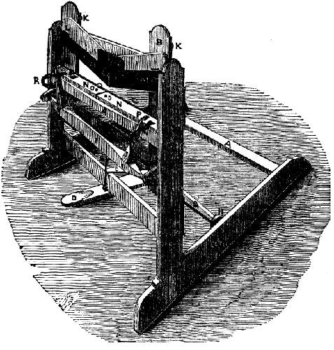
A A A are the pieces forming a strong wooden main frame, which is portable and stands upon a floor. B B, are the pieces forming a strong wooden frame which is made to slide up and down, on cast-iron guides between the vertical posts of the main frame, by means of a spring, C-C, which is attached to the upper edge of a cross piece of the main frame at C, and to the under edge of the sliding frame at C. and a treadle, D, which connects with the sliding frame by means of a jointed iron rod, E, and plate, F. This treadle is connected with a cross piece, G, which works on journals, as fulcra let into blocks, H, which are secured to the insides of the sills of the main frame. On the front side and near the upper end of the sliding frame, B, are two adjustable pieces of hard wood, I I, connected by means of a thin, flexible iron plate, J. These pieces are secured to the sliding frame, so as to be adjustable to any angle required for the tapering ends of the stave by means of set screws, K K, and draw bolts, L L. There being also two like draw bolts through the plate, J, for securing the centre. Besides the obtuse angle at which the two pieces are adjustable in regard to each other, they are also permanently secured to the sliding frame by means of the same set screws and draw bolts, at another angle, so that the two connecting ends shall be several inches below the outside ends. To the lower sides of these two pieces, I I, the upper steel shearing knives, M M, are let in nearly flush with the pieces, II, and secured thereto by screws. Upon the upper cross piece of the main frame, A. there are two adjustable pieces, N N, made of some hard wood secured to the cross piece, at their inner ends, by means of screws, 0 0, and at their outer ends by means of draw bolts, PP, the heads of which are let into a mortise so as to be flush on the top--the stems of the bolts passing through oblong holes in the pieces, N N, and are thus capable of being set to suit the angle of the upper knives, M M.
On the edges of these two adjustable pieces, the lower steel knives, Q Q, are secured by screws, their cutting edges being level with the upper sides of the pieces, N N. Near each outer end of the adjustable pieces, N N, there is permanently secured an iron guide, R R, which connects at its lower end by an adjustable screw, W, to the main frame. The cross piece upon which the pieces, N N, rest is slightly beveled on the upper side, or, the pieces, N N, are bevelled so that the latter may be adjusted by means of set screws, P P, and the guides, R R, to suite the radial bevel required on the edges of the stave, in accordance with the intended diameter of the barrel. In front and some distance below the bevelled pieces, N N, a revolving gauge, 5 5, is secured upon journals at the ends, in adjustable bearing pieces, T T, secured by a screw, V, and plate. The two projections on the upper side of this gauge, pass up a little above the guides, R R, and are placed each, soas to gauge the proper width of each end of the stave to be jointed.
The mode of operation of this machine is as follows:--After the upper shearing knives, M M, are adjusted to suit the taper required on the stave, the lower shearing knives, Q Q, are adjusted to match them, and so that, upon the descent of the upper knives, shearing contact of the edges of the two sets of knives shall commence at the angle, U, and gradually extend towards each outer end, until their whole cutting edges have passed each other. In order to give the proper radial bevel to the edges of the stave, in accordance with the required diameter of the barrel, the bevelled pieces, N N, are also adjusted at the same time by means of the adjustable guides, R R, and screws, W, so as to suit this required bevel. The machine being now ready for use, the workman takes one or more stavees, and places them along the pieces, N N, and with his hand on each end, brings them in contact with the upper projections of the movable gauge, holding the connections firmly, the staves are slidden along on the duides and pieces, N N, over the lower knives--his foot is then pressed down firmly and quickly upon the treadle, D, when the sliding frame and its knives are brought down, draw cutting or shearing the edges of the staves from their middle towards their ends. The staves are now reversed, and the opposite edges cut or jointed in the same manner.
The claim is for the adjustable knife with the adjustable rest. More information may be obtained by letter addressed to the patentee. |
|
 Stave jointing machine
|
|