|
Title: |
1858 Article-William Sellers & Co., Boring & Turning Lathe |
|
Source: |
The Engineer, 16 Apr 1858, pg. 296 |
|
Insert Date: |
5/4/2025 9:34:10 AM |
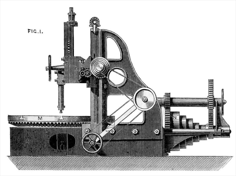
This is an American invention, by William Sellers, of Philadelphia, and consists in constructing lathes without the usual face chucks and long supporting shafts; the principle of the invention being that of supporting the face plates on supports as near the peripheries as possible, and combining an adjusting stop or centre bearing with an outer support.
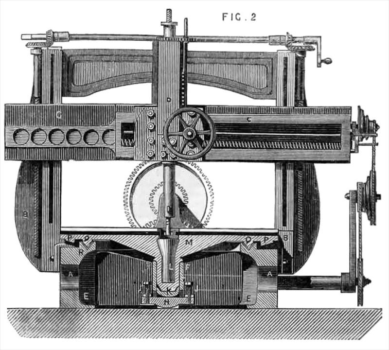
Fig, 1 is a side view: and Fig. 2 a cross section through the centre of the spindle. The object of the improvement is to impart greater solidity to the revolving plate upon which the work is to be operated on is secured, and an to arrange the machine as to make it complete in itself and not be dependent upon stone or brick foundations for the support of the spindle of the revolving plate, as hitherto necessary in large machines. To this end the bed piece A is made of sufficient depth to give support to the uprights B, B, which carry the slide rest C, C, and tool slide D; the bed A is formed on its underside as a plate, which rests on my suitable support for the machine and the slide rest and tool slide are of any desired character, and adapted to hold any tool suitable for operating on the article placed on the bed. In the centre of the machine and attached to the bottom plate E, a barrel F is made which is supported laterally by the braces g, g, having at its lower end openings on opposite sides to receive the cross bar H, which is supported at its extremities by the set screws J, J, resting on the bottom plate E. The set screws are of sufficient length to give a small vertical adjustment to the cross bar H, which supports the step k. The vertical adjustment to the step k may be obtained by the use of one set; screw beneath it, or by the use of a wedge in place of the cross bar H, should it he found more convenient. The step k rests upon the cross bar H an as to prevent it turning and the place of support is rounded, so that should one of the set screws be raised more than the other, it may not prevent the upper surface from ?tting accurately to the bottom of the spindle L, which is attached to the under surface of the face plate M. The step k and spindle L are accurately fitted in the barrel E, which serves as a short bearing for the spindle and a lateral support for the step.
Motion in communicated from the driving pulley N to the faceplate M by means of the bevel pinion O and wheel P, or other suitable device. On the underside of the face plate M, an annular rib of metal Q is made, of such form as may best sustain the revolving plate in every direction; the V form usually adopted on planing machines is preferred, as the oil is thus retained in contact with the revolving plate. This annular rib Q rests in a corresponding and reversed piece R, formed on or attached to the bed piece A. To put the machine in working order the bar H is adjusted vertically by means of the set screw J, J, so that nearly all the weight of the face plate M may rest upon step k, the remainder being supported in the annular groove R on the bed piece A. By this arrangement the vertical and horizontal strain upon the face pate M, which is due to the cut of the tool, will he mainly taken upon the groove R, and the greater the distance of the tool from the centre of the plate, the more service will the outer support be to the operation of the machine. The form of the groove may be varied, or one side be taken any altogether.
Images Courtesy of http://www.gracesguide.co.uk
US Patent: 17,641
https://www.datamp.org/patents/displayPatent.php?number=17641&typeCode=0 |
|
 1858 William Sellers & Co., Boring & Turning Lathe
 1858 William Sellers & Co., Boring & Turning Lathe (Front View)
|
|