|
Title: |
1855 Article-John McDowall & Sons., Wood-Planing Machine |
|
Source: |
The Practical Mechanics Journal, V8 Oct 1855 pgs. 103-104 |
|
Insert Date: |
8/19/2015 9:43:57 PM |
WOOD-PLANING MACHINE
Planing machines for timber, as we have already endeavoured to show, owe much to the inventive talent and constructive skill of Mr. Mc‘ Dowall, who, by directing his attention almost exclusively to wood-working machinery, has largely contributed to the advancement of a class of mechanical contrivances which would otherwise have run some risk of falling behind in the course of the general industrial improvements of the age. The improvements which we now bring forward comprehend a newly-arranged planing machine, with a silent feed motion of differential action-a “silent feed motion” for sawing machinery — and a new arrangement of combined roughing and finishing cutters for “thicknessing."
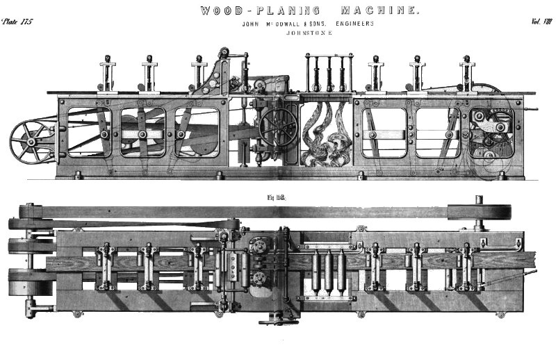
Fig. 1, in the plate, is a complete longitudinal elevation of the improved planing machine, as in working order, with a board in the act of passing through it to be planed. Fig. 2 is a corresponding plan of the machine. The entire apparatus is carried upon the long main vertical side standards, A, cast in suitable lengths, and bolted down to the foundation by lugs, as at B. These frames are connected together by transverse end-pieces and tie-rods, to form a strong rectangular carrying-frame; and at one end of it is the first motion driving shaft, C, shown as broken away from its actuating power. This shaft has an inner end-bearing in one of the side standards, and it carries the large first motion-strap pulley, D, giving motion to the whole of the cutting movements. From this pulley, a broad open strap, E, passes to a small pulley, F, on the outer end of a cross shaft, G, running in bearing brackets, H, bolted to the framing at the opposite end of the machine. This shaft also carries an outside pulley, I, from which a crossed strap, J, passes back to a small pulley, K, on the shaft of the compound rotatory planing cutter, L, for planing the upper surface of the board or flooring deal, M. The spindle of this cutter is carried in vertically adjustable end-bearings, N, fitted to the vertical edges of the bracket standards, O, which are bolted down on the upper edges of the main framing pieces. The cross shaft, G, also carries a pair of equal-sized strap pulleys, P, whence twisted straps, Q, pass to the two broad pulleys, R, on the vertical spindles of the two cutter heads, S, which cut the edges of the wood, and, if necessary, tongue and groove them. These two latter cutter-spindles are carried in bearings, T, on horizontal dovetail slide-pieces, U, adjustable at different distances on each side the longitudinal centre of the machine, by the action of two screw-spindles, one of which is actuated by the outside hand-wheel, V, whilst the other spindle, which is only to be shifted occasionally, is adjustable by a key, to be shipped on to the square head, W, on the opposite side of the machine. The front spindle carries a fine pitched worm, X, in gear with a horizontal worm-wheel, it, fast on the spindle of a small index-hand, which points to a graduated arc, Z, and thus indicates the exact “ set” of the cutters for the particular breadth of timber under treatment.
As the deal is passed into the machine to be planed, it is first of all entered beneath the nipping feed-cams, a, which carry it continuously forward to the cut. Each nipping arrangement consists of a horizontal traversing plate of metal, b, tongued at its opposite ends, to slide freely but accurately in corresponding grooves in the top plates, c, of the standards; and upon these plates, c, are attached a pair of vertical parallel standards, d, connected at their upper ends by a light cross bar, e, which answers as well for the bearings of the overhead cross adjusting spindle, f, for the “set” of the nippers. Each standard, d, is slotted down its centre, to receive and guide the traversing nut-bearings, g, of the cross cam-spindle, h, a screw-spindle, i, being passed down from above, and through the nuts, g, so as to enable the cam-spindles, h, to be set up or down by the screw action. This screw action is worked, when necessary, by handles shipped on to the end of the cross spindle, f, by the workman, who thus works the screws, simultaneously through the two pairs of small bevel wheels, j. Each cam-spindle, h, has an eccentric cam, a, loosely hung upon it by an eye, the cam-eye being entered upon the spindle up against an adjustable collar, k, on the latter; and the cam-spindle, h, is set fast in the standard slots by the outside adjusting-nut, i. Thus arranged, the nipper forms a complete traversing frame, capable of free horizontal movement along its guide grooves. Beneath the level of its traverse support, two projecting eye-pieces, m, are cast on the plate, b, each eye carrying a joint stud, n, whence short links, o, pass to corresponding eyes, p, on the upper ends of the two sides of the vibrating lever frame-piece, q. Each frame is carried on a stud centre, r, in the framing, and each has a bottom joint-eye, s, for connection, by a link-rod, t, to the actuating cam-feed mechanism at the front or entering end of the machine. Each frame has also a heavily-weighted bent lever, u, attached to its bottom cross bar, and contrived so as to tend to draw the frame continually backward in the opposite direction to the traverse of the wood.
The primary movement is given to the entire series of these nipping feeders-of which there are six altogether, three being at each end of the machine—-by a toothed pinion, v, on the first motion shaft. This pinion gears with a large toothed wheel, w, set on a cross shaft, x, and carrying a second pinion, y, in gear with a second spur-wheel, z, fast on the actuating cam-shaft, 4. On this shaft are keyed the three separate cams, or differential eccentric pieces, 1, 2, 3. Opposite to, and over the periphery of each cam, is set an antifriction pulley, 5, carried on the horizontal arm of a bell-crank lever, 6, the three bell-cranks being carried loosely on a stud shaft, 7. The longer vertical arms of these bell-cranks are connected by eyes, 8, at their lower ends to the respective rods, 6, which are severally linked, as already described, by end and intermediate eyes, to the bottom of each of the nipping frames. The three cams are so set at starting, that they shall each act at different periods of the revolution of their carrying shaft, in such a manner that a uniform feed action may be given to the board passing through the machine. In other terms, they are set at equal distances asunder in the direction of the revolution of their shaft, each cam being linked to and made to actuate two nippers. Thus, the corresponding nippers of each pair have always the same relative position, as marked 1, 2, and 3. Then, as the planing goes on, and the cams revolve, each pair of nippers is made to traverse forward say in the direction of the arrows at 1 by the upward revolving action of the corresponding cam. This forward traverse is the positive feed action; for the moment the nipping frame moves in this direction, the prominent eccentric portions of the cams, a, 1, are thereby carried down, or jammed hard upon the upper surface of the timber, squeezing it firm down upon the bottom plates, b, so that the timber is carried forward to the cut, as if it were permanently attached to the nipping feed-frame. Whilst this positive feed is being given to the wood, the two pairs, 2, of the nippers are being brought back by the action of their weighted levers, as their corresponding cam is descending in its revolution; these two nippers are consequently slipping over the wood, for, on the instant of the return movement towards the entering end of the machine, the prominences of the nipping cams are drawn out of nipping contact, and the frames go back without interfering with the feed traverse of the wood in the forward direction. As delineated in the plate, the third pair of nippers are still in forward gear, and acting, by reason of the position of their actuating cams, to carry forward the wood in concert with the nippers, 1. By this means, as each cam comes round, it gives its forward feed and back traverse in regular uniform succession, each succeeding nipper gradually relieving the last in feeding action. And although two nippers always thus tend to come into action at the same time, derangement cannot ensue from this cause, inasmuch as the quickest forward feeding nippers at any given moment carry forward the wood free of the other nippers, which give way in their nipping action to the higher rate of motion, by reason of the consequent slip or disengagement of the nipping cam. In this way the feed is constantly uniform, as although it is furnished by three separate actions, yet each only comes into actual feeding play at the moment that it is required to keep up the regularity of movement.
As the board is thus carried forward, it comes first above the three finishing planes in the frame, 9, over which it is held down by the three rollers, 10, which run in adjustable bearings held down by the helical springs, 11, adjustable to any desired tensional pressure by the nuts, 12, on their screwed spindles, 13, carried in the stationary frames, 14. After passing these pressers, the emerging end of the wood, as planed and finished on its under surface, proceeds beneath the duplex pressing pulleys, 15, set on a stud centre in the free end of a lever arm, 16, fast to the horizontal shaft, 17, carried in end bearings, 18, in the end frame, and held down by the lever and weight, 19. Thence it enters beneath the pair of horizontal pressing rollers, 20, similarly held down by adjustable helices, 21; and it is between these two rollers that the planing of the upper surface takes place. At the moment, however, of its passage beneath the duplex pulley, 15, it is first acted upon by the two cutting heads, s. In the present example these cutters are arranged for tongueing and grooving the opposite edges of the flooring deal, as is usual in laying flooring. Thus, in the elevation, fig. 1, the two square cutters, 22, take off the two angles of one edge of the deal, leaving the central feather or tongue standing up, whilst the other double angular single cutter, 23, takes off the sharp angles from the tongue. Again the opposite cutter head, for the other side, carries three plain central grooving cutters, 24, for producing the plain groove, whilst a. fourth duplex cutter, 25, is added, to shave off the angular edges in a similar way. This completes the edge finish of the board, and the latter then being held well down by the rollers, 20, is submitted to the action of the rotatory cutter, or “thicknesser,” L, for bringing the upper side of the wood to a fair level, and equalizing the thickness of the deal.
The thicknessing cutter,L, in the plate, is a plain rotating blade of the usual kind; but in figs. 3, 4, 5, and 6 of the wood engravings annexed, we have shown two other forms of rotatory cutters of differential action. The first of these cutters both rough-cut and finish at once. Fig. 3 is a longitudinal view, and fig. 4 a cross section of this cutter. It is driven by a band pulley, A, as in the plate, fast on the end of a spindle, with a squared central portion, B, on the two opposite sides of which are set the two cutter plates, C. Each of these plates is cut or slotted out transversely, like a comb, as at D, so as to form a series of regularly disposed cutters; and the two plates being precisely similar, they are so set on the spindle as to “break joint," as it were, in their action upon the deal. In other words, as one cutter comes round, it cuts out a series of strips of wood corresponding to the size and arrangement of the cutting edges; whilst the other, or succeeding cutter, then comes into action, and takes off the prominent strips left by the first one. To make a clean smooth cut, the relative cuts of the two cutters are made to overlap each other slightly in their action. With this arrangement, the whole of the cutting edges may be accurately ground up and sharpened at one operation; and one setting of the plate, by means of the dovetail bolts, n, which pass out from longitudinal dovetail grooves in the spindle, through slots in the plate, sets the whole range of cutters. The cutter represented in the corresponding views, figs. 5 and 6, is a “rougher" only. The spindle is carried in a similar way, but it is slotted clear through its central rectangular portion to receive the alternated roughing cutters, A, B, which are put in in directions reverse to each other, so as to present cutting edges on opposite sides alternately, the series being spaced out by intermediate gauge or setting pieces. The spindle is bored out at one end to receive the adjusting binding screw, C, by which the whole of the cutters may be screwed hard up against the solid end of the holding slot. This affords facility of adjustment of the cutters to suit various purposes, and the effect is, that, in working, the cutters remove the over wood or rough surface in shallow strips, so that, when the finishing cutter follows, it makes a clean smooth surface with little difficulty, and there is less liability to tear out large areas of the wood from the surface. After leaving the cutter, L, in the plate, the deal is in its finished state, and it has then simply to be drawn completely through by the nipper arrangement.
In the nipping traverser, or silent feed motion, for sawing purposes, the deal is nipped between two flat clipping pieces of metal, just as it is between the cam and bottom cross plate in the planing machine. These nippers are hinged in pairs to traversing frames, so as to have an alternate angular nipping action and a release movement. These frames are actuated by cranks on shafts, geared together with elliptical spur-wheels, in such manner that the constant uniform revolution of the first motion shaft gives a differential rotation to the actuating cranks, and, through them, to the traversing frames. This plan is particularly well suited for sawing, as the elliptical wheels are so set in reference to the sawing action, that the deal has a slow forward traverse in to cut, whilst the empty nipper returns at a rapid rate, the nipping and slipping actions of the feeders being effected simply by the corresponding traverse and angular position of the two frames.
This feed motion is capable of ready and exact adjustment to suit every variety of circumstances in cutting timber; and the result of this capability is a clear gain of twenty per cent in the work performed, as compared with that done in a similar space of time by means of former contrivances. This will he understood, on remembering that in saw frames, as usually made, not less than half a tooth of feed change can be made; whilst one-tenth of a tooth might be sufficient for the time being. The “silent feed motion” removes this great defect, by providing for any fractional amount of change of feed, to suit any depth or quality of wood, without occasioning g the slightest loss of time in working. Fig. 7 in our wood engravings is a side view of the motion complete. The actuating motion is derived from a rocking-shaft, A, of the usual kind, carrying a slotted lever, B. In the central slot of this lever is a screw-spindle, C, carrying an end hand-wheel, D; so that, by turning this wheel, the nut, E, upon it may be traversed nearer to, or further from, the centre of the shaft, A, and so affect the amount of feed. The nut, E, has jointed to it a connecting-rod, F, the other end of which is jointed at G to the working carriage, H. This carriage embraces the outer and inner parts of the rim of the wheel, I, by means of the palms, J, K; and owing to the peculiar construction and connection of these palms, the upward traverse of the rod, F, places the line of the centres, G, L, at an angle with the neutral radial line, M; thus causing the palms to collapse and nip the wheel rim, and carry it round a portion of a turn, the amount of which is regulated by the working lever, as already described. As the lever, B, descends, the centres, G, L, tend towards the neutral line of action, M, when no movement of the wheel can occur, as the under carriage, N, is at once put into oblique action in the same manner as the upper one—thus resisting any tendency of the wheel to go back, whilst the upper carriage descends to make a fresh stroke. Both carriages are constructed alike. The upper one is represented as advancing the timber; the lower one is fixed at any part of the frame to the stationary centre of the link, O, and is represented as inert, or in neutral action. When the feed motion is to be suspended, to allow the wheel to revolve freely without the occurrence of the nipping action of the palms, the necessary modification is effected by the hand-wheels, P. In each carriage socket, Q, there is a screw, which, on turning the hand-wheel, P, brings the carriage into the neutral line of action, and retains it there; when the wheel, I, may turn freely either way, until the palms are brought back into feeding play by the reverse turning of the wheels, P. The socket, Q, and palm, J, are cast into one piece, and this piece being placed within a holding frame, has a partial rolling motion on the pin, R, as a centre. Between the faces of the socket, Q, and the fiat portion of the carriage, as at n, is an indie-rubber washer, which, by its elasticity, keeps both parts united, in readiness for instantaneous action, and, at the same time, prevents the faces from being abraded by the frequent impact which occurs in working.
This feed motion may he applied to any frame at present in use, as it is immaterial what diameter the feeding wheel may be. It is only necessary that the wheel may be truly turned internally and externally and that the palms be well to the turned surfaces. |
|
 1855 John McDowall & Sons., Wood-Planing Machine
 1855 John McDowall & Sons., Wood-Planing Machine (Cutter Bars)
 1855 John McDowall & Sons., Wood-Planing Machine (Brake)
|
|