|
Title: |
1855 Article-John McDowall & Sons., Stationary Cross-Cut Sawing Machine |
|
Source: |
The Practical Mechanic's Journal, Volume 8, Aug 1856 pg. 247 |
|
Insert Date: |
8/20/2015 12:58:41 PM |
Stationary Cross-Cutting Machine
In our illustrated article of last month on the subject of timber sawing, we detailed an ingenious invention of Mr. Mc‘Dowall’s, for effecting the periodical traverse or shift of a circular cross-cut saw, the saw disc being brought up to, and removed from its work, so that the timber requires no shifting, whilst the whole of the cutting apparatus is capable of being stowed clear away beneath the mill floor. Such an arrangement is of course intended to meet special circumstances, for there are many sawing Operations wherein a stationary machine is equally well adapted for cross-cutting purposes; and we now engrave a stationary machine of reciprocatory action, also invented by Mr. Mc‘Dowall, and erected by his firm in the laboratory of the Woolwich Arsenal.
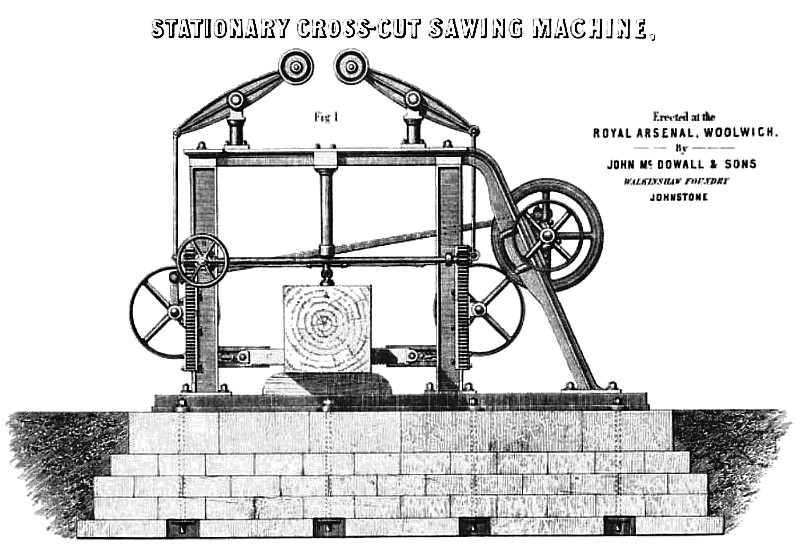
Our Plate 186 affords three several combined views of this machine. Fig. 1 is a front elevation of the sawing apparatus, as in the act of severing a log; and figs. 2 and 3 are opposite edge views corresponding. The end of the log, A, placed to be cut, is held down to the foundation by a vertical screw-box, B, abutting against the top cross beam of the saw framing. Motion is communicated to the saw, C, by a driving belt passed over the pulley, D, set on a short crank shaft, running in pedestal hearings on the upper part of the inclined frame pieces on the right of the machine. The driving pulley, with its counterpart loose pulley, is placed on one overhanging end of the crank shaft, and the other end carries a crank lever, G, jointed to one end of a long transverse connecting rod, F, the opposite end of which rod is similarly jointed to a longer crank lever, G, on the opposite side of the framing. This lever, G, is fast upon the end of a short shaft, oscillating in hearings upon a slide on the vertical standard pieces of the framing, and carrying a large belt pulley, B an exactly similar pulley, I, is placed on the driving side of the machine; and these two pulleys serve to carry an endless belt, composed of two lengths of flexible steel belting, and adjustable link rod, and the saw blade. The saw, O, has its parallelism of action preserved by a pair of opposite end guides, J; a flexible steel belt is fastened to each end of the saw, at the part where the latter is set in its horizontal slides, and these two belts being respectively passed round the pulleys, H, I, they are joined to the two ends of the link rod, K;, which has a box screw at its centre, to enable the tension upon the saw to be adjusted at pleasure. As the main driving pulley continuously revolves, and with it the crank lever, is, the connecting rod, R, communicates a reciprocatory action to the longer lever, O, and thus the continuous reciprocatory action of the saw is secured, just as in the “high-speed tensional sawing machine" of the same inventor, given in our Plate 123, vol. 6.
The vertical standards of the frame carry two planed slides, L, each of which has a toothed rack attached to it. The cross shaft, M, carried in bearings upon the fixed portion of the frame, has upon each end of it a spur pinion, and these two pinions gear with the toothed racks of the slides. The hand-wheel, N, affords the means of turning the shaft, it, through the intervention of a bevel wheel and pinion, so that the attendant can thus easily raise or lower the saw as his work may require. The weighted beams, O, oscillating upon studs in the tops of the pillars, P, carried on the top cross bar of the framing, act as counterbalances for the weight of the saw and slides, their outer ends being respectively connected by descending links with the adjusting slides: with this system of balancing, the labour of adjustment is very light. This machine has been for some time in full and successful operation in the Royal Arsenal. |
|
 1856 John McDowall & Sons., Stationary Cross-Cut Sawing Machine
 1856 John McDowall & Sons., Stationary Cross-Cut Sawing Machine (Side Views)
|
|